Vertiv | eSure™ Rectifier Module User Manual (UM1R483500e3) | Rev. H
Table 6:
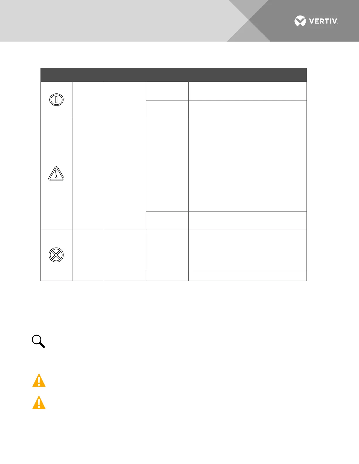
Rectifier Indicators
Indicator Normal State Alarm State Alarm Cause
Power
(Green)
On
Off
No input voltage.
Internal input fuse open.
Flashing
The rectifier is being identified by the
controller.
Protection
(Yellow)
Off
On
AC input under/over voltage.
PFC output under/over voltage.
Moderate load sharing imbalance.
Rectifier not inserted into the slot
completely.
Rectifier over-temperature protection.
Rectifiers are operating in an output power
derating mode (rectifiers derate when
rectifier temperature rises above or input
voltage falls below acceptable values).
Rectifier in ECO Standby Mode when ECO
Mode is active in controller.
Flashing
Loss of communication with the controller
(the rectifier can provide power).
Alarm
(Red)
Off
On
Severe load sharing imbalance.
Rectifier output disabled for any reason,
including overvoltage shutdown and
internal output fuse open.
Rectifier addresses contradictory.
Fan not operating (rectifier shuts down).
Installing Rectifiers
Rectifiers can be inserted or removed with power applied (hot swappable).
NOTE!
Each rectifier module locks into a module mounting shelf by means of a latch located on the
bottom of the rectifier. The latch and rectifier handle are interactive. Pushing the handle up into the
rectifier’s front panel causes the latch to extend to the locking position; pulling the handle down out from
the rectifier’s front panel causes the latch to retract. See
Figure 6
.
CAUTION! Double pole/neutral fusing. All-pole circuit breaker should be provided when used in IT
power system, or if N line cannot be distinguished during field installation.
WARNING! To prevent damage to the latching mechanism, ensure the handle is in the open position
when installing or removing a rectifier. NEVER hold the handle in the closed position when installing a
rectifier into a shelf.

 Loading...


