Static Pressure Max Pause
Maximum initial length of time that fan speed stops increasing after the pressure reading crosses into the deadband.
After the pause, the fan speed pulses (increases if below the setpoint and decreases if above the setpoint) for the
period selected in the Static Pressure Pulse inside deadband field. After each pulse, a pause takes place, the length of
which is calculated as a ratio between the deadband border (minimum) and the setpoint (maximum).
Static Pressure Pulse Inside Deadband
Period of time the fan speed increases or decreases (pulses) when pressure is inside the deadband.
Static Pressure Requested Speed Up To
Temperature at which static pressure control override begins.
3.1.14 Supply Sensor Aggregation
When more than one supply air sensor is required to be used for cooling capacity control (temperature control), the Supply
Sensor Aggregation feature may be enabled. Supply Sensor Aggregation feature allows the use of multiple temperature
sensors which are programmed to create a single, aggregated supply air temperature value which may be used for cooling
capacity control.
Vertiv™ Liebert® iCOM™ shall support a maximum of (6) sensors for Supply Sensor Aggregation calculation. Up to (5)
additional remote 2T sensors may be connected to a given Liebert® iCOM™ controller and programmed for Supply Sensor
Aggregation. The standard Supply NTC sensor may also be included/excluded in the aggregated supply temperature
calculation Liebert® iCOM™. The end user shall have the ability to determine whether the supply sensor aggregation
calculated value is based on the Average of all the sensor values or Maximum (worst case) temperature reading. Invalid
sensor readings will not affect the unit calculation (they will be excluded).
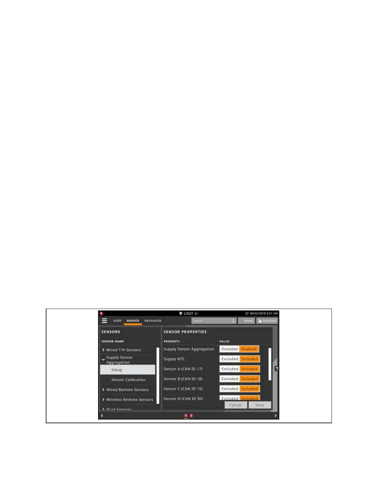
Enabling Supply Sensor Aggregation
Via the Liebert® iCOM™ display, navigate to Service Menu > Auxiliary Device Setup > Sensors > Supply Sensor Aggregation
Setup.
Figure 3.13 Enabling Supply Sensor Aggregation
3 Service Operation
49
Vertiv™ Liebert® iCOM™Installer/User Guide
 Loading...


