66250240 - V2.0 - 31/10/18
- 1 -
4000 Series
Art.4838 - Installation instructions
A
B
C
C
D
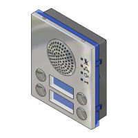
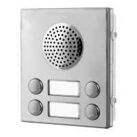
Fig. 1 Front
5
PTE
C
NC
NO
BSY
SL
F1
LB
T
CB
COM
P1
1
2
+12
GND
P2
P3
P4
DIP-SWITCH 1 SETTINGS (8 way)
MELODIES
1,2
RINGS
3,4
SPEECH TIME
5,6
DOOR OP. TIME
7,8
SWITCHES
SETTINGS
OFF OFF
OFF ON
ONOFF
ON ON
MELODY 1
MELODY 2
MELODY 3
MELODY 4
2 RINGS
4 RINGS
6 RINGS
8 RINGS
30s
60s
90s
120s
1s
4s
8s
16s
DIP-SWITCH 2 SETTINGS (3 way)
STATUS
FUNCTION
SWITCHES
OFF
ON
OFF
ON
Reassurance tone disabled
Reassurance tone enabled
"4+1" System (standard)
"5+1" System (privacy of speech)
OFF
ON
1
2
3
Made in Italy
DIP-SW 1 DIP-SW 2
Normal operation
Recall on handset pick up (only "4+1")
4838-0
4838-1
4838-2
4838-1D
4838-2D
Stainless Steel Matte
Aluminium
High Brass
E
F
HG
I
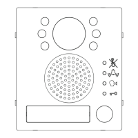
Fig. 2 Back
DESCRIPTION
Art.4838 series speaker units are intelligent devices with a built-in
microprocessor to control the operations. This speaker unit oers
easy of installation (on audio door entry systems with multiple en-
trances there are no audio entrance Art.502N switchers required)
and assists the user by providing a number of visual and acoustic
signals during normal system operation (call, conversation etc).
The speaker unit circuitry includes:
• The microprocessor;
• The transmitting amplier with condenser microphone and
volume control;
• The receiving amplier and volume control;
• 2 LEDs to illuminate the name plate (except Art.4838-0).
• 4 LEDs for operation visual signalling;
• The lock release relay to enable the electric lock;
• The modulated tone generator;
• Two programming dip-switches one 3 way and one 8 way.
This speaker unit together with a camera module Art.4830, can
be used on video door entry systems. On systems with two or
more entrances, there is no video entrance exchangers Art.892
required. Standard Art.506N relays can be used instead.
LEGEND
A
Loudspeaker
B
LEDs
C
Push buttons
D
Card namers holders
E
Loudspeaker volume
F
Microphone volume
G
8 way dip-switch
H
3 way dip-switch
I
Connection terminals
AVAILABLE VERSIONS
Art.4838-0
1
Art.4838-1
1
2
Art.4838-2
13
Art.4838-1D
13
42
Art.4838-2D
LEDS
The rst LED (red), if switched ON, indicates that it is
not possible to make a call because a call or a conver-
sation is in progress (from the outdoor station from
which you are calling or from another outdoor station
on system with multiple entrances).
The second LED (red), if switched ON, indicates that a
call is in progress. The LED will be switched OFF when
the call is answered.
The third LED (yellow), if switched ON, indicates that it is
possible to speak. The LED will be switched OFF at the end
of conversation (or at the end of the conversation time).
The fourth LED (green), if switched ON, means that the
door lock has been operated. It will be switched OFF at
the end of the “door opening” time.
CONTROLS
Loudspeaker volume
Adjust the loudspeaker volume.
Rotate clockwise to increase or anti-clockwise to decrease
Microphone volume
Adjust the microphone volume.
Rotate clockwise to increase or anti-clockwise to decrease
Art.4838 Speaker unit for audio door entry systems “4+1”, “5+1” with
privacy of speech, intercommunicating and video