Viale Vicenza, 14
36063 Marostica VI - Italy
www.vimar.com
49401510A0 01 2106
4622.036B
Network Connection
5
MENU
IPC
Network Cable Network Cable
Switch
Router
Computer
● Access Through IP-Tool
① Make sure that the camera and the PC are connected to the local
network.
② Install IP-Tool from the CD and run it after installation.
Device Network Search
Immediate Re fresh
name
name
name
IPC
IPC
IPC
unknown
unknown
unknown
192.168. 226 .201
192.168. 1.2
192.168. 1.3
80
80
80
9008
9008
9008
255.255.
255.255.
255.255.
Modify Net wor k Parameter
Mac Addr ess
IP Addr ess
Modify
CE :98 :23 :75 : 35 :2 2
192 . 16 8 . 226 . 2 01
255 . 255 . 255 . 0
192 . 16 8 . 226 . 1
i
Tip: Enter the adminis tra tor password, and
then modif y the n etwork parameters.
Total Device : 3
Local IP Address:192.1 68. 1.4
Subne t Mas k:2 55.255. 255 . 0 Gateway: 1 92. 168. 1.1 DNS:210. 21 . 196. 6
Device Nam e Dev ice Type IP Addr ess Http Port Data Port
Subnet
Product Mo del
About
Subne t Mas k
Gateway
Restore IPC Default Configuration
⑤ Install the dome and enclosure to the mounting base.
(a). Loosen the nut from the main element.
b . Run the network cable (without RJ 45 connector) through the
both elements. Then crimp the cable with RJ 45 connector.
c . Connect the cable to the hermetic connector. Then tighten the
nut and the main cover.
( )
( )
(a)
(b)
( )
c
④ Secure the mounting base to the ceiling or wall with the screws provided.
Then adjust the dome to obtain an optimum view angle.
0 ~75° °
0 ~360° °
0 ~360° °
⑥ Finally, fix the camera with the fixed screw.
Fixed screw
③ Modify the IP address. The default IP address of this camera is
192.168.226.201. Click the information of the camera listed in the
above table to show the network information on the right hand.
Modify the IP address and gateway of the camera and make sure its
network address is in the same local network segment as the
computer’s. Please modify the IP address of your device according
to the practical situation.
Mac Address
IP Address
Modify Network Parameter
Modify
CE :98 :23 :75 :35 :22
192 .168 . 1 . 201
255 . 255 . 255 . 0
192 .168 . 1 . 1
Subnet Mask
Gateway
For example, the IP address of your computer is 192.168.1.4. So the
IP address of the camera shall be changed to 192.168.1.X. After
modification, please enter the password of the administrator and click
“Modify” button to modify the setting.
The default password of the administrator is “123456”.
④ Double-click the camera listed in the IP-Tool or manually enter
the IP address in the address bar of the web browser to connect IP
camera. Then follow directions to download and install the plugin.
⑤ Enter the username and password in the login interface.
The default username is admin; the default password is 123456.
450043001853 A0
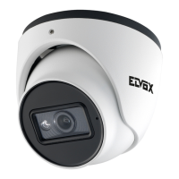
Telecamera Dome IP a colori Day & Night, sensore CMOS 1/2,8", risoluzione
2 Mpx (1920x1080), obiettivo fuoco fisso 3,6 mm, filtro IR meccanico, H.265 e
H.264 Multistream, funzioni AV, alimentazione PoE o 12 Vdc, IR 20-30 m, funzioni
WDR, 3DNR, HLC, BLC, Mask, Motion, Smart IR, RTSP, protocollo ONVIF, grado
di protezione IP67. Dimensioni: Ø 95x83 mm. Peso 430 g.
Contenuto della confezione
Una volta ricevuto il dispositivo, controllare gli accessori indicati di seguito. Le illu-
strazioni sotto riportate hanno solo funzione di riferimento. Far riferimento all'appa-
recchiatura in dotazione.
Introduzione
Questa telecamera IP (abbreviato in IP-CAM) è stata progettata per fornire soluzioni
TVCC ad elevate prestazioni. Adotta chip di elaborazione video allo stato dell'arte.
Utilizza le tecnologie più avanzate, di codica e decodica video ed è conforme al
protocollo TCP/IP, SoC.(System on chip) ecc. per assicurare la stabilità e l'adabilità
del sistema. I manuali completi e i software CVM.exe, Iptool.exe e Diskcalculator.exe
sono disponibili nella scheda prodotto consultabile nel sito www.vimar.com
Connessioni
Di seguito sono riportate le principali connessioni della telecamera.
ENIT
Installazione
Prima di iniziare, assicurarsi che la parete o il sotto siano sucientemente solidi
per sopportare tre volte il peso della telecamera. La procedura di montaggio è la
seguente:
1) Allentare la vite di ssaggio per smontare la telecamera.
2) Praticare i fori per le viti e per il cavo sulla parete utilizzando la dima di foratura.
3) Passare i cavi e collegare il cavo di alimentazione e il cavo di rete.
4) Fissare la base di montaggio della telecamera alla parete con le viti, come
descritto di seguito.
5) Prima della regolazione, visualizzare l’immagine della telecamera su un moni-
tor per regolare l’angolo di visuale della telecamera, quindi ssare la ghiera con
la vite di ssaggio.
6) Per completare l'installazione rimuovere delicatamente la pellicola di protezione.
Installation
Before start, please make sure that the wall or ceiling is strong enough to withstand
3 times the weight of the camera. The mounting steps are as follows:
1)
Loosen the xed screw to disassemble the camera.
2)
Drill the screw holes and the cable hole on the wall according to the drill template
.
3) Route the cables and connect the power cable and video cable.
4) Secure the mounting base with camera to the wall with screws as shown below.
5) Before the adjustment, display the image to a monitor and then adjust the camera
and then loosen the xed ring to adjust the view angle of the camera angle. Final-
ly, x the camera with the xed screw.
6) Remove the protective lm to complete the installation procedure.
Telecamera
Camera
Istruzioni per l’uso
Quick and start guide
Dima di foratura
Drill template
Viti
Screws & spiles
Cacciavite
Screw-driver
Cappuccio impermeabile
Water-proof Cap
Introduction
This IP-camera (short for IP-CAM) is designed for high performance CCTV solu-
tions. It adopts state of the art video processing chips. It utilizes most advanced
technologies, such as video encoding and decoding technology, complies with the
TCP/IP protocol, SoC (System on chip), etc to ensure this system more stable and
reliable. Complete manuals and CVM.exe, Iptool.exe e Diskcalculator.exe software are
available to download in the Product info sheet section of www.vimar.com website.
Connections
Here below the main connections of the camera.
IP Dome Day&Night colour camera, CMOS 1/2.8" sensor, 2 Mpx (1920x1080) res-
olution, 3.6 mm fixed focus lens, mechanic IR filter, H.265 and H.264 Multistream,
VA functions, PoE or 12 Vdc supply, IR 20-30 m, WDR, 3DNR, HLC, BLC, Mask,
Motion, Smart IR, RTSP functions, ONVIF protocol, IP67 protection degree.
Dimensions: Ø 95x83 mm. Weight 430 g.
Package content
After you receive your device, please check the following accessories. The pictures
here are for reference only.
1 Cavo di rete / Network Cable
2 Cavo alimentazione / Power Cable
3 Base di ssaggio / Mounting base
4 Vite di ssaggio / Fixing screw
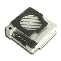
5 Microfono / Microphone
6 Slot micro SD card / Micro SD card slot
7 Reset
1 2
Installazione della base
Base mounting
4
5
Montaggio alla base
Mounting to the base
Ø51,0 mm
Ø4,5 mm
Ø91,6 mm
44,2 mm
38,2 mm
Package
Overview
Installation
1
2
3
4
Warning and Caution
■ If the product does not work properly, please contact your dealer
or the nearest service center. Never attempt to disassemble the
camera yourself. (We shall not be responsible for any problems
caused by unauthorized repair or maintenance.)
■ Do not allow water or liquid intrusion into the camera.
■ In the use of the product, you must be strict compliance with the
electrical safety regulations of the nation and region. When the
product is mounted on wall or ceiling, the device shall be firmly
fixe
d.
■ Do not use camera beyond specified voltage range.
■ Do not drop the camera or subject it to physical shock.
■ Avoid touching the camera lens.
■ If cleaning is necessary, please use clean cloth to wipe it gently.
■ Do not aim the camera at the sun or extra bright place.
■ Do not place the camera in extremely hot, cold (the operating
temperature shall be -30˚C~60˚C), dusty or damp locations, and do
not expose it to high electromagnetic radiation.
■ To avoid heat accumulation, good vent
ilation is required for
operating environment.
Quick Start Guide
Network Camera
Camera
Quick
start guide
CD
Plastic
plug ×3
Drill template
Screwdriver
Tapping screws × 3
■ Please read this instruction carefully before operating the
unit and keep it for further reference.
■ All the examples and pictures used here are for reference only.
■ The contents of this manual are subject to change without
notice.
* 1 It is recommended to install the security cap for outdoor installation.
* 2 If the PoE switch is used to power the camera, DC12V power supply is not
required.
Security Cap
Ethernet connector
Micro SD card slot
Power connector
Reset
1
5
2
6
3
7
4
Fixed screw
Mounting base
Fixed Screw
Mounting Base
Enclosure
Dome
1
2
3
4
5
6
7
DC12V
Microphone
Please make sure that the wall or ceiling is strong enough to
withstand 3 times the weight of the camera. Please install and use
the camera in the dry environment.
① Loosen the fixed screw to disassemble the camera.
② Unscrew the cover of the dome and then insert a micro SD card.
After that, install back the cover and make sure the cover is installed
firmly.
Insert a micro SD card
Cover
③ Drill the screw holes and the cable hole on the ceiling according
to the drill template. Then route and connect the cables.
Earth wire connection
(mm)
Ø4.5
Ø51.0
Ø91.6
44.2
38.2
Package
Overview
Installation
1
2
3
4
Warning and Caution
■ If the product does not work properly, please contact your dealer
or the nearest service center. Never attempt to disassemble the
camera yourself. (We shall not be responsible for any problems
caused by unauthorized repair or maintenance.)
■ Do not allow water or liquid intrusion into the camera.
■ In the use of the product, you must be strict compliance with the
electrical safety regulations of the nation and region. When the
product is mounted on wall or ceiling, the device shall be firmly
fixe
d.
■ Do not use camera beyond specified voltage range.
■ Do not drop the camera or subject it to physical shock.
■ Avoid touching the camera lens.
■ If cleaning is necessary, please use clean cloth to wipe it gently.
■ Do not aim the camera at the sun or extra bright place.
■ Do not place the camera in extremely hot, cold (the operating
temperature shall be -30˚C~60˚C), dusty or damp locations, and do
not expose it to high electromagnetic radiation.
■ To avoid heat accumulation, good vent
ilation is required for
operating environment.
Quick Start Guide
Network Camera
Camera
Quick
start guide
CD
Plastic
plug ×3
Drill template
Screwdriver
Tapping screws × 3
■ Please read this instruction carefully before operating the
unit and keep it for further reference.
■ All the examples and pictures used here are for reference only.
■ The contents of this manual are subject to change without
notice.
* 1 It is recommended to install the security cap for outdoor installation.
* 2 If the PoE switch is used to power the camera, DC12V power supply is not
required.
Security Cap
Ethernet connector
Micro SD card slot
Power connector
Reset
1
5
2
6
3
7
4
Fixed screw
Mounting base
Fixed Screw
Mounting Base
Enclosure
Dome
1
2
3
4
5
6
7
DC12V
Microphone
Please make sure that the wall or ceiling is strong enough to
withstand 3 times the weight of the camera. Please install and use
the camera in the dry environment.
① Loosen the fixed screw to disassemble the camera.
② Unscrew the cover of the dome and then insert a micro SD card.
After that, install back the cover and make sure the cover is installed
firmly.
Insert a mic ro SD card
Cover
③ Drill the screw holes and the cable hole on the ceiling according
to the drill template. Then route and connect the cables.
Earth wire conne ction
(mm)
Ø4. 5
Ø51 .0
Ø91 .6
44. 2
38. 2
Network Connection
5
MENU
IPC
Network Cable Network Cable
Switch
Router
Computer
● Access Through IP-Tool
① Make sure that the camera and the PC are connected to the local
network.
② Install IP-Tool from the CD and run it after installation.
Device Network Search
Immediate Re fresh
name
name
name
IPC
IPC
IPC
unknown
unknown
unknown
192.168. 226 .201
192.168. 1.2
192.168. 1.3
80
80
80
9008
9008
9008
255.255.
255.255.
255.255.
Modify Net wor k Parameter
Mac Addr ess
IP Addr ess
Modify
CE :98 :23 :75 : 35 :2 2
192 . 16 8 . 226 . 2 01
255 . 255 . 255 . 0
192 . 16 8 . 226 . 1
i
Tip: Enter the adminis tra tor password, and
then modif y the n etwork parameters.
Total Device : 3
Local IP Address:192.1 68. 1.4
Subne t Mas k:2 55.255. 255 . 0 Gateway: 1 92. 168. 1.1 DNS:210. 21 . 196. 6
Device Nam e Dev ice Type IP Addr ess Http Port Data Port
Subnet
Product Mo del
About
Subne t Mas k
Gateway
Restore IPC Default Configuration
⑤ Install the dome and enclosure to the mounting base.
(a). Loosen the nut from the main element.
b . Run the network cable (without RJ 45 connector) through the
both elements. Then crimp the cable with RJ 45 connector.
c . Connect the cable to the hermetic connector. Then tighten the
nut and the main cover.
( )
( )
(a)
(b)
( )
c
④ Secure the mounting base to the ceiling or wall with the screws provided.
Then adjust the dome to obtain an optimum view angle.
0 ~75° °
0 ~360° °
0 ~360° °
⑥ Finally, fix the camera with the fixed screw.
Fixed screw
③ Modify the IP address. The default IP address of this camera is
192.168.226.201. Click the information of the camera listed in the
above table to show the network information on the right hand.
Modify the IP address and gateway of the camera and make sure its
network address is in the same local network segment as the
computer’s. Please modify the IP address of your device according
to the practical situation.
Mac Address
IP Address
Modify Network Parameter
Modify
CE :98 :23 :75 :35 :22
192 .168 . 1 . 201
255 . 255 . 255 . 0
192 .168 . 1 . 1
Subnet Mask
Gateway
For example, the IP address of your computer is 192.168.1.4. So the
IP address of the camera shall be changed to 192.168.1.X. After
modification, please enter the password of the administrator and click
“Modify” button to modify the setting.
The default password of the administrator is “123456”.
④ Double-click the camera listed in the IP-Tool or manually enter
the IP address in the address bar of the web browser to connect IP
camera. Then follow directions to download and install the plugin.
⑤ Enter the username and password in the login interface.
The default username is admin; the default password is 123456.
450043001853 A0
Network Connection
5
MENU
IPC
Network Cable Network Cable
Switch
Router
Computer
● Access Through IP-Tool
① Make sure that the camera and the PC are connected to the local
network.
② Install IP-Tool from the CD and run it after installation.
Device Network Search
Immediate Re fresh
name
name
name
IPC
IPC
IPC
unknown
unknown
unknown
192.168. 226 .201
192.168. 1.2
192.168. 1.3
80
80
80
9008
9008
9008
255.255.
255.255.
255.255.
Modify Net wor k Parameter
Mac Addr ess
IP Addr ess
Modify
CE :98 :23 :75 : 35 :2 2
192 . 16 8 . 226 . 2 01
255 . 255 . 255 . 0
192 . 16 8 . 226 . 1
i
Tip: Enter the adminis tra tor password, and
then modif y the n etwork parameters.
Total Device : 3
Local IP Address:192.1 68. 1.4
Subne t Mas k:2 55.255. 255 . 0 Gateway: 1 92. 168. 1.1 DNS:210. 21 . 196. 6
Device Nam e Dev ice Type IP Addr ess Http Port Data Port
Subnet
Product Mo del
About
Subne t Mas k
Gateway
Restore IPC Default Configuration
⑤ Install the dome and enclosure to the mounting base.
(a). Loosen the nut from the main element.
b . Run the network cable (without RJ 45 connector) through the
both elements. Then crimp the cable with RJ 45 connector.
c . Connect the cable to the hermetic connector. Then tighten the
nut and the main cover.
( )
( )
(a)
(b)
( )
c
④ Secure the mounting base to the ceiling or wall with the screws provided.
Then adjust the dome to obtain an optimum view angle.
0 ~75° °
° °
0 ~360° °
⑥ Finally, fix the camera with the fixed screw.
Fixed screw
③ Modify the IP address. The default IP address of this camera is
192.168.226.201. Click the information of the camera listed in the
above table to show the network information on the right hand.
Modify the IP address and gateway of the camera and make sure its
network address is in the same local network segment as the
computer’s. Please modify the IP address of your device according
to the practical situation.
Mac Address
IP Address
Modify Network Parameter
Modify
CE :98 :23 :75 :35 :22
192 .168 . 1 . 201
255 . 255 . 255 . 0
192 .168 . 1 . 1
Subnet Mask
Gateway
For example, the IP address of your computer is 192.168.1.4. So the
IP address of the camera shall be changed to 192.168.1.X. After
modification, please enter the password of the administrator and click
“Modify” button to modify the setting.
The default password of the administrator is “123456”.
④ Double-click the camera listed in the IP-Tool or manually enter
the IP address in the address bar of the web browser to connect IP
camera. Then follow directions to download and install the plugin.
⑤ Enter the username and password in the login interface.
The default username is admin; the default password is 123456.
450043001853 A0
Network Connection
5
MENU
IPC
Network Cable Network Cable
Switch
Router
Computer
● Access Through IP-Tool
① Make sure that the camera and the PC are connected to the local
network.
② Install IP-Tool from the CD and run it after installation.
Device Network Search
Immediate Re fresh
name
name
name
IPC
IPC
IPC
unknown
unknown
unknown
192.168. 226 .201
192.168. 1.2
192.168. 1.3
80
80
80
9008
9008
9008
255.255.
255.255.
255.255.
Modify Net wor k Parameter
Mac Addr ess
IP Addr ess
Modify
CE :98 :23 :75 : 35 :2 2
192 . 16 8 . 226 . 2 01
255 . 255 . 255 . 0
192 . 16 8 . 226 . 1
i
Tip: Enter the adminis tra tor password, and
then modif y the n etwork parameters.
Total Device : 3
Local IP Address:192.1 68. 1.4
Subne t Mas k:2 55.255. 255 . 0 Gateway: 1 92. 168. 1.1 DNS:210. 21 . 196. 6
Device Nam e Dev ice Type IP Addr ess Http Port Data Port
Subnet
Product Mo del
About
Subne t Mas k
Gateway
Restore IPC Default Configuration
⑤ Install the dome and enclosure to the mounting base.
(a). Loosen the nut from the main element.
b . Run the network cable (without RJ 45 connector) through the
both elements. Then crimp the cable with RJ 45 connector.
c . Connect the cable to the hermetic connector. Then tighten the
nut and the main cover.
( )
( )
(a)
(b)
( )
c
④ Secure the mounting base to the ceiling or wall with the screws provided.
Then adjust the dome to obtain an optimum view angle.
0 ~75° °
0 ~360° °
0 ~360° °
⑥ Finally, fix the camera with the fixed screw.
Fixed screw
③ Modify the IP address. The default IP address of this camera is
192.168.226.201. Click the information of the camera listed in the
above table to show the network information on the right hand.
Modify the IP address and gateway of the camera and make sure its
network address is in the same local network segment as the
computer’s. Please modify the IP address of your device according
to the practical situation.
Mac Address
IP Address
Modify Network Parameter
Modify
CE :98 :23 :75 :35 :22
192 .168 . 1 . 201
255 . 255 . 255 . 0
192 .168 . 1 . 1
Subnet Mask
Gateway
For example, the IP address of your computer is 192.168.1.4. So the
IP address of the camera shall be changed to 192.168.1.X. After
modification, please enter the password of the administrator and click
“Modify” button to modify the setting.
The default password of the administrator is “123456”.
④ Double-click the camera listed in the IP-Tool or manually enter
the IP address in the address bar of the web browser to connect IP
camera. Then follow directions to download and install the plugin.
⑤ Enter the username and password in the login interface.
The default username is admin; the default password is 123456.
450043001853 A0
Vite di
ssaggio/
Fixed
screw