Aerobar installation
1. Ensure handlebar is compatible with steerer tube. Make certain that the diameter of the steerer tube matches the Vision Metron Snakebite Stem Steerer Clamp size 1-1/8” (28.6mm).
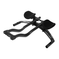
2. Install base bar ① to stem first by selecting the desired base bar height. The Metron TFA Aerobar Base Bar ① can have a +/-25mm drop or rise depending on which direction the base bar is placed in the Stem Body ⑤.
3. Slide Metron TFA Base Bar ① into the slot on the Stem Body ⑤. Place the Conical Bar/Stem Fixing Nut ③ into the two holes immediately right and left of the housing port under the stem. Use Stem Fixing Bolt ⑥ and screw into
the Conical Bar/Stem Fixing Nut ③. Torque to 60 kgf.cm / 6 Nm / 53 in.lbs. Note: be careful not to clamp brake housing or electronic wiring when installing the Stem Fixing Bolts ⑥ or Conical Stem/Bar Fixing Nuts ③.
4. Assemble Upper Angle Adjustment Bracket ⑮ and Aero Extension Armrest Mount ⑯ together using Angle Adjustment Bolt ⑳ and Angle Adjustment Grip Nut ⑭
5. Slide Aero Extensions ○
27
into Aero Extension Mount ⑯. Set to desired length and rotation angle. Tighten Angle Adjustment Bolt ⑳ to torque of 70 kgf.cm / 7 Nm / 62 in.lbs., then tighten Extension Fixing bolts ⑲ to 40 kgf.cm
/ 4 Nm / 35 in.lbs..
Ensure the minimum insertion length indication on the Aero Extensions ○
27
(MIN^INSERT) is beyond the Aero Extension / Armrest Mount ⑯ ends. Riding the bar without the “MIN^INSERT” line inside the mount
can cause damage and unexpected bar failure causing accident and injury.
6. Place Lower Angle Adjustment Bracket ⑬ under Upper Angle Adjustment Bracket ⑮ making sure to align the wiring groves. Torque Extension Width Spacer Bolts ② to 70 kgf.cm / 7 Nm / 62 in.lbs.
7. To adjust angle of aerobar extensions ○
27
, Use a 5mm hex key loosen two or three full turns all 4 Extension Width Spacer Bolts ② then with a 6mm hex key to loosen the Angle Adjustment Bolt ⑳ until Angle Adjustment Grip
Nut ⑭ slides freely. Set to desired angle and tighten Angle Adjustment Bolt ⑳ with Angle Adjustment Grip Nut ⑭ to 70 kgf.cm / 7 Nm / 62 in.lbs. Torque Extension Width Spacer Bolts ② to 70 kgf.cm / 7 Nm / 62 in.lbs.
8. Install Bridge ○
22
with Bridge Fixing Bolts ○
23
insuring that wiring grooves on left and right-angle adjustment assemblies are both facing the same direction and back. Alternating torque bolts to 60 kgf.cm / 6 Nm / 53 in.lbs.
9. Install Armrest Adjustment Plates ⑰ for desired fit position using Armrest Adjustment Plate Bolts ⑱. Torque to 20 kgf.cm / 2 Nm / 18 lbf.in.
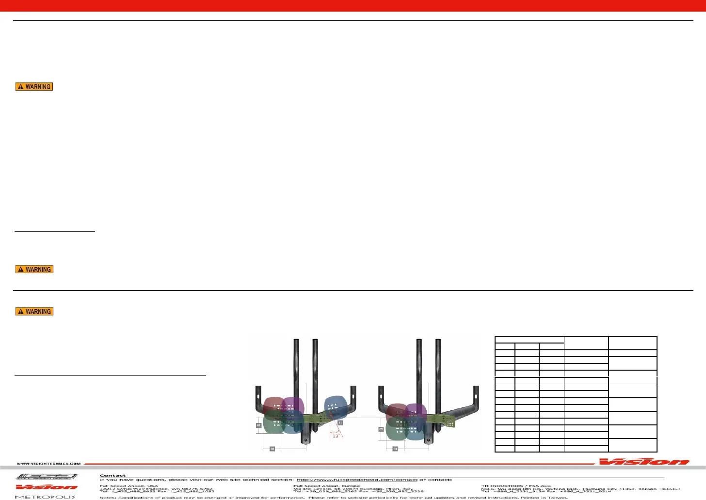
10. See Table 1 for Stack Spacers ⑩, ⑪, ⑫ and bolt configuration to adjust the Aero Extension/Armrest Mounts ⑯ to the desired height.
11. Install Armrest Pad Plate ○
24
, Evenly tighten Armrest Plate Fixing Bolts ○
25
. Do not tighten above 20 kgf.cm / 2 Nm / 18 lbf.in.
12. Remove the adhesive Velcro Strips from Armrest Pads ○
26
and attach to the top surface of left and right Armrest Pad Plate ○
24
.
13. Install the Expander Assembly ④ into the Carbon Steerer. Tighten the Expander Assembly with a 6mm hex wrench to 60-90 kgf.cm / 6-9 Nm / 53-80 in.lbs. of torque.
14. Place the Stem Body ⑤ onto the Carbon Steerer, tighten the Compression Cap & Bolt ⑦ with a 4mm hex wrench to until proper bearing preload is achieved. Note: Proper bearing preload is apparent when there is no “knock”
(fore / aft or up / down free play) in the headset assembly, while the bearings rotate freely (free steering motion).
15. Ensure handlebar is aligned straight and gradually tighten the Steerer Clamp Bolt ○
29
, by alternating turning each screws 1/4 to 1/2 turn at a time so both screws tighten simultaneously to 60 kgf.cm / 6 Nm / 53 in.lbs DO NOT
exceed maximum torque specification. Always use a calibrated torque wrench.
16. Install Stem Top Plate ⑧ to Stem Body ⑤ use Stem Top Plate Bolt ⑨ Torque to 10 kgf.cm /1 Nm / 9 in.lbs.
Wiring Installation Tips
1. Brake/electronic wiring should be run through the Metron TFA Aerobar Base Bar ① before installing Stem Body ⑤ or Aero Extension/Armrest Mounts ⑯.
2. Installation is greatly improved when using a guide cable to gently pull the housing or electronic wires through the base bar from either direction.
3. If Armrest Stack Spacers ⑩, ⑪, ⑫ are being used in conjunction with wired electronic shifting on the Aero Extensions ⑯, use electrical tape to hold wiring in the guide slots on the spacers. Small ports on either side of the Stem
Body ⑤ are designed ONLY to allow electronic shifting wires to be run internally through the Stem Body ⑤ if desired.
Never attempt to modify the cable guide holes. Do not drill, saw, or file the holes larger or to a different shape. Modifications will void warranty and may result in failure of the handlebar while riding causing accident,
Aero Extension Length Adjustment
It may be necessary to trim aero extensions if the rear of the extension protrudes behind the mount. Aerobars can only be cut from the rear. Do NOT cut the aerobars extensions from the front. Cutting aerobars from the front will
void the warranty. Make careful measurments before cutting and be sure of the cut location. Cutting an aero extension is a one-time and final adjustment.
Do not cut beyond the (MIN^INSERT) line indicators on the extensions. Cutting beyond the line indicators may make it impossible to install shifters into the extensions.
1. Use a sharp hacksaw blade for best results on alloy aerobars. For carbon aerobars, an abrasive blade will work best. Apply a layer of tape around area to be cut to reduce possibility of carbon fraying while cutting.
2. Use a cutting guide for the saw blade to ensure an even cut of the aerobar. Cut the extension to desired length.
3. Remove any burrs or frayed carbon strands with sand paper.
4. Install shifter per shifter manufacturer’s instructions.
5. Aero Extension Front and Rear Plug ○
28
, ○
21
over cable housing
and press into Aero Extension ○
27
.
Armrest Adjustment
Spacers
5mm
10mm
20mm
Stack Heights
② Bolt length
0 0 0 0mm 25mm
1 0 0 5mm
0 1 0 10mm
35 mm
1 1 0 15mm
0 0 1 20mm
45 mm
1 0 1 25mm
0 1 1 30mm
55 mm
1 1 1 35mm
0 0 2 40mm
65 mm
1 0 2 45mm
0 1 2 50mm
75 mm
1 1 2 55mm
0 0 3 60mm
85 mm
1 0 3 65mm
0 1 3 70mm
95mm
Table 1: Armrest Stack Spacer & Bolt Compatibility
 Loading...