DE5110 1
0$(67520$(6752'/
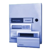
Computerized, Multi-Function 8 to 16 Zone Alarm
Control/Communicator
Installation Instructions
Table of Contents
1. INTRODUCTION
2
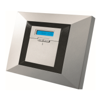
5. KEYPAD DISPLAY UNITS
12
1.1 S
stem Overview 2 5.1 Ke
pad t
pes 12
1.2 List of Components 2 5.2 LED ke
pads KP-1001/8 and KP-1001/16 12
1.3 S
stem Confi
urations 3 5.3 KP-1003 - Ke
pad with Lar
e LCD 14
2. SPECIFICATIONS
3 5.4 KP-1002 - Ke
pad with Re
ular LCD 14
2.1 General Data 3 5.5 Mountin
the Ke
pad/Displa
Units 14
2.2 Communicator Characteristics 4 5.6 Connectin
the Ke
pad to the Bus 15
2.3 Siren Driver Data 5
6. EXP-1600 ZONE EXPANDER OPTION
15
2.4 Ph
sical Properties 5 6.1 Description and Use 15
3. THE ALARM CONTROL CABINET
5 6.2 Mountin
16
3.1 Alarm Control Module Description 5 6.3 Wirin
17
3.2 Power Pack Kit PK-1 5
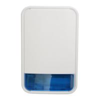
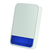
7. SIR-1000 SIREN DRIVER OPTION
18
3.3 Optional Enhancement Kits 6 7.1 Description and Use 18
3.4 Mountin
the Alarm Control Cabinet 7 7.2 Mountin
18
3.5 Wirin
the Alarm Control Module 7 7.3 Wirin
18
3.6 Software and Hardware Reset 9
8. KEYPAD BUS LENGTH CONSIDERATIONS
18
4. DL-1000 TWO-WAY COMMUNICATOR
10 8.1 Problem Anal
sis 18
4.1 Description and Use 10 8.2 Technical Data 19
4.2 Operation Routine 10 8.3 Calculatin
Method 19
4.3 Mountin
12
APPENDIX A - REMOTE AND LOCAL COMPUTER
20
4.4 Wirin
12
APPENDIX B - SYSTEM DATA RECORD
21