PowerMaxExpress
M@bile Connect
Quick Reference Guide
STOP!
Make a cup of tea, and spend the next
ve minutes reading this information
1. Introduction
Welcome to PowerMaxExpress M@bile Connect, the wireless
home security solution with onboard GSM/GPRS communication
module. This kit is designed for simple installation and reporting
via SMS messaging or to a central monitoring centre.
L This is a professional product and should be installed by a
qualied engineer!
Before you begin you should know that this kit is supplied with
the transmitters pre-enrolled and pre-programmed with the
most common settings. Additionally, each transmitter is labelled
with its zone or fob number on the rear plastic. Following this
guidewillhelpyoumakebasiccongurationchanges,formore
detailed information please refer to the full programming guide
included within the kit.
Finally….we have included a trouble shooting section to this
guide. BEFORE you ring the support line have a look through as
most common problems are listed here.
SIM CARD INFORMATION – (UK Customer Only)
Within this kit a Pay as You Go SIM pack is provided complete
with £5.00 of credit available. Details on managing and top-
ping up this SIM card are within the pack.
We recommend that the SIM is only used for SMS applications
and is managed by the end user on completion/handover of the
system. Installations connected to a central monitoring centre
should use a contract SIM provided by your Central Station,
Distributor or Network provider.
2. Choose a Location to Mount your Control Panel,
making sure it is at least 1m from any large metallic objects e.g.
radiators, RF equipment or WiFi transmitters. Additionally think
about the best position for a mobile network signal and ensure
there is access to a mains power supply. We recommend you test
the network signal and sensor strengths before mounting the
panelintoitsnalposition.
Before powering-up the PowerMax make sure the SIM card is
thebatteryrst,whichclipsintothecompartmentonthemain
panel, and then connect the lead from the transformer to the VAC
socket. The backup battery may take an hour to reach full capacity,
during this period the panel will report “CPU Low Battery”.
L Depending on the status of the panel and accessories
the display will show [READY – MEMORY] or [NOT READY –
MEMORY]. At any time you can press the status button on
the keyfob, or repeatedly press
to review the faults/
memory conditions that are outstanding.
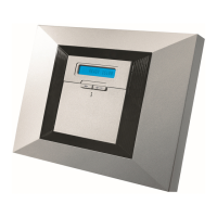
1
230VAC connection
2
Fixing points
3
GSM module and SIM
holder
4
ACyingleadconnection
5
Battery holder
6
Hardwired Zone
7
Connector for optional
GSM/GPRS antenna
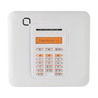
1
Three easy-to-use
navigation buttons
2
Three easy-to-use
operation buttons for
quick arming/disarming
3
Full function 20-button
keypad
4
Chime enable/disable
5
Emergency
6
Fire
+ Panic