Vivax-Metrotech Corp. (Headquarters)
3251 Olcott Street, Santa Clara, CA 95054, USA
T/Free: 1-800-446-3392 Tel: +1-408-734-1400 Fax: +1-408-734-1415
Email: SalesUSA@vxmt.com Website: www.vivax-metrotech.com
Visit us at www.vivax-metrotech.com to view our full product line and worldwide locations.
1
2
3
4
5
6
7
8
Percentage signal strength
Peak level indicator
Gain setting
Bar graph signal strength indicator
Signal direction (SD) forward/backward arrows
Compass line direction indicator
Left/Right direction to target line indicators
Frequency selection
2 Frequency selectedDepth and current readings
Target line
Lines of confidence (closer these are to the target line indicates
more confidence)
Arrow indicates the direction to move towards the line.
1
3
4
5
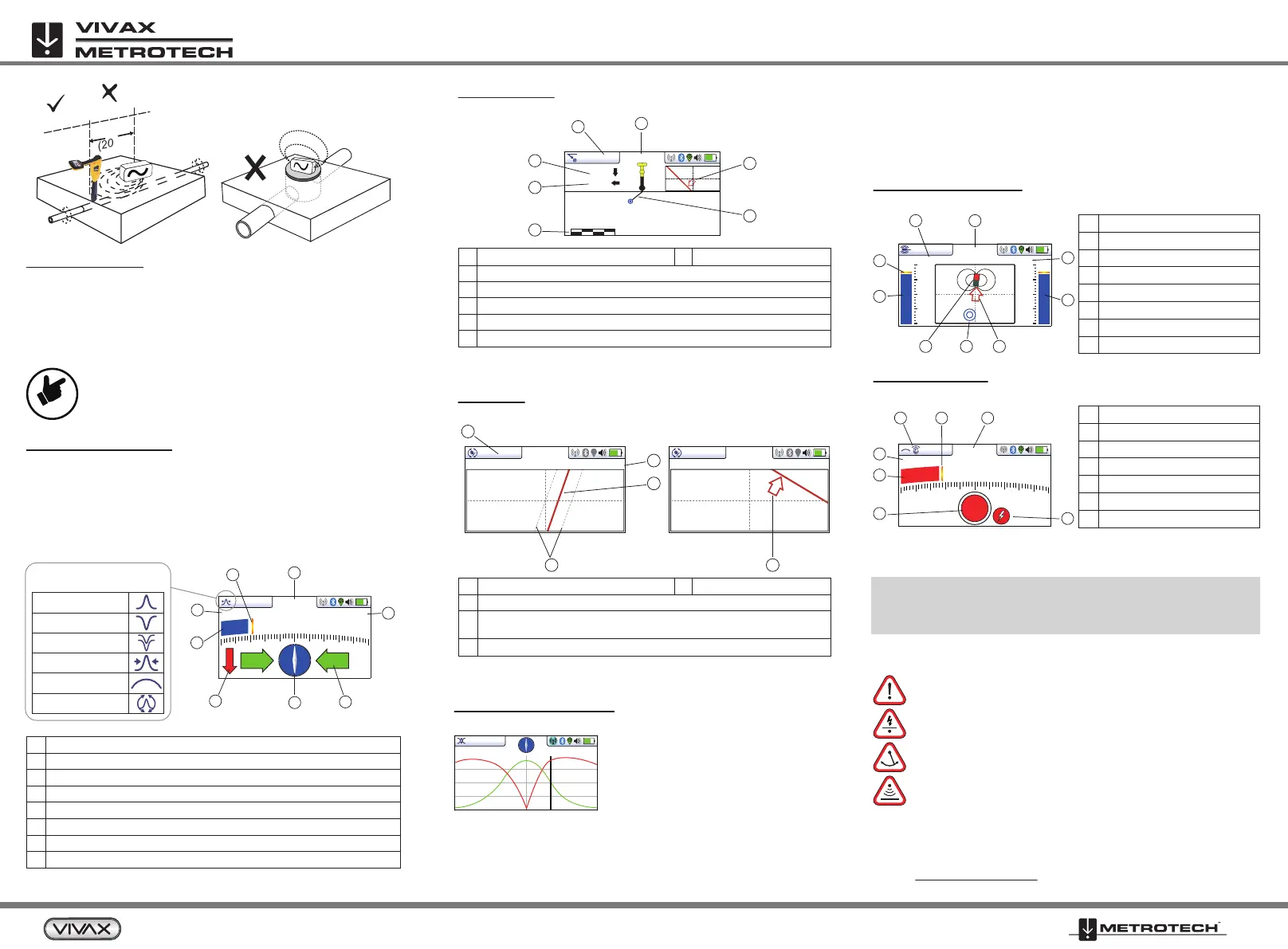
Plan View (Refer to the vLoc3 Series manual)
Shows a picture as if you were viewing the line from above the ground.
Advantages: Automatic gain adjustment; easy finding/routing of lines with
the 3D mode.
Advantages: Automatic gain adjustment; line depth is permanently
measured, even when running offset to the line.
Vector Screen (Refer to the vLoc3 Series manual)
Shows a cross-sectional view through the ground.
8.19kHz
1.43m
1.86m
0 2m
85.6mA
3
2
1
6
7
4
5
14’5’’
4
3
2
1
12.9mA 32.8kHz
5
14’5’’
12.9mA 32.8kHz
1
3
4
5
6
7
Frequency selected
Vertical distance to the target
Horizontal distance to the target
Scaling (adjust with +/- keys)
Shows plan view of the target
Cross-section view that shows vectors to target
Signal current
2
Classic locate modes (refer to the vLoc3 Series manual)
Available modes: peak, peak with arrows, null, broad peak, delta
null, omni direction.
The individual modes within the classic view can be changed by a
short press (<1 sec.) on the "Enter" button. If a mode is not visible
or not desired, it can be switched on or off in the user menu (long
press on the "i" key / classic display/selection with "Enter" key).
Locate Screens**
For all subsequent locating views, except Transverse Graph
and Sonde Mode:
The distortion level is displayed on the bar graph.
Green = low interference, Blue = some interference, and Red = high
interference level, treat the locating results with caution.
NOTE:
Locating views (classic, vector, plan view,
transverse graph, and sonde can be changed by a
long press on the "Enter" key (approx. 2 seconds).
Antenna
configuration:
50ft
(20m)
d
d
0.39m
18.3
17dB 116mA
SD-USA
3
2
1
4
5
6
7
8
Peak
Null
Delta-Null
Peak with arrows
Broad peak
Omni direction
If the signal path is distorted, or the two signal peaks are not on the
centerline, there is interference in the electromagnetic field. To
determine the cable's exact position now, please refer to the user
manual, section "Distorted fields."
Advantages: Automatic gain adjustment; Optimal analysis of signal distortion.
Peak signal detector
Signal strength bar graph
Sonde icon
Null point
Direction to sonde
Frequency selection
Numeric signal level
Gain setting
1
2
3
4
5
6
7
8
Bar graph gain setting
Signal strength from marker
Marker detection ball
Marker type graphic
Numeric value of bar graph
Peak level indicator
Marker icon
1
2
3
4
5
6
7
Sonde Location Mode (Refer to the vLoc3 Series manual)
Locating non-metallic pipes with a sonde.
67.2
25dB
8kHz
2
2
3 4 5
6
8 7
1
*
**
Observe the manual's safety instructions regarding handling the
devices, measurement results, and Li-ion batteries!
Read the exact settings, evaluations, and safety instructions for
locating in the user manual!
Advantages: Simple marker location with immediate depth measurement at
the push of a button. For more details on the dual-mode with parallel line and
marker location, please refer to the user manual.
Marker detection - Pinpointing EMS Markers
Valid for vLoc3-ML or vLoc3 receiver with vLoc3-MLA attached.
19.1
12dB
1
2
3
4
7 6 5
The target line is below the receiver
when both signal peaks are on the
center line and the signal is not distorted.
The centerline does not indicate the
target line but serves as an orientation
for the two signal peaks and the cable's alignment!
3’9”
33dB 14.1mA 8.19kHz
Transverse Plot Screen (Refer to the vLoc3 Series manual)
Analyze the field shape at a particular location.
Signal overload - When the receiver is too close to the
inductive operated transmitter or a power transformer.
Shallow cable - When the cable is possibly less than 6-inches
deep. Proceed with caution!
Swing alert - When excessively swinging the receiver. Doing
so could result in misleading information.
Overhead cable - When the signal is mainly radiating from
above distorting the below-ground signal.
Warnings - Are audible sound with a vibration of the handle. Warnings
can be activated or deactivated in the user menu.
4 5
www.vivax-metrotech.com
6
NOTE
 Loading...