2
Installation Guidelines
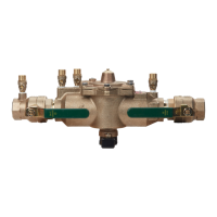
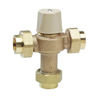
Series 007 and LF007
1
⁄2" – 2"
Indoors
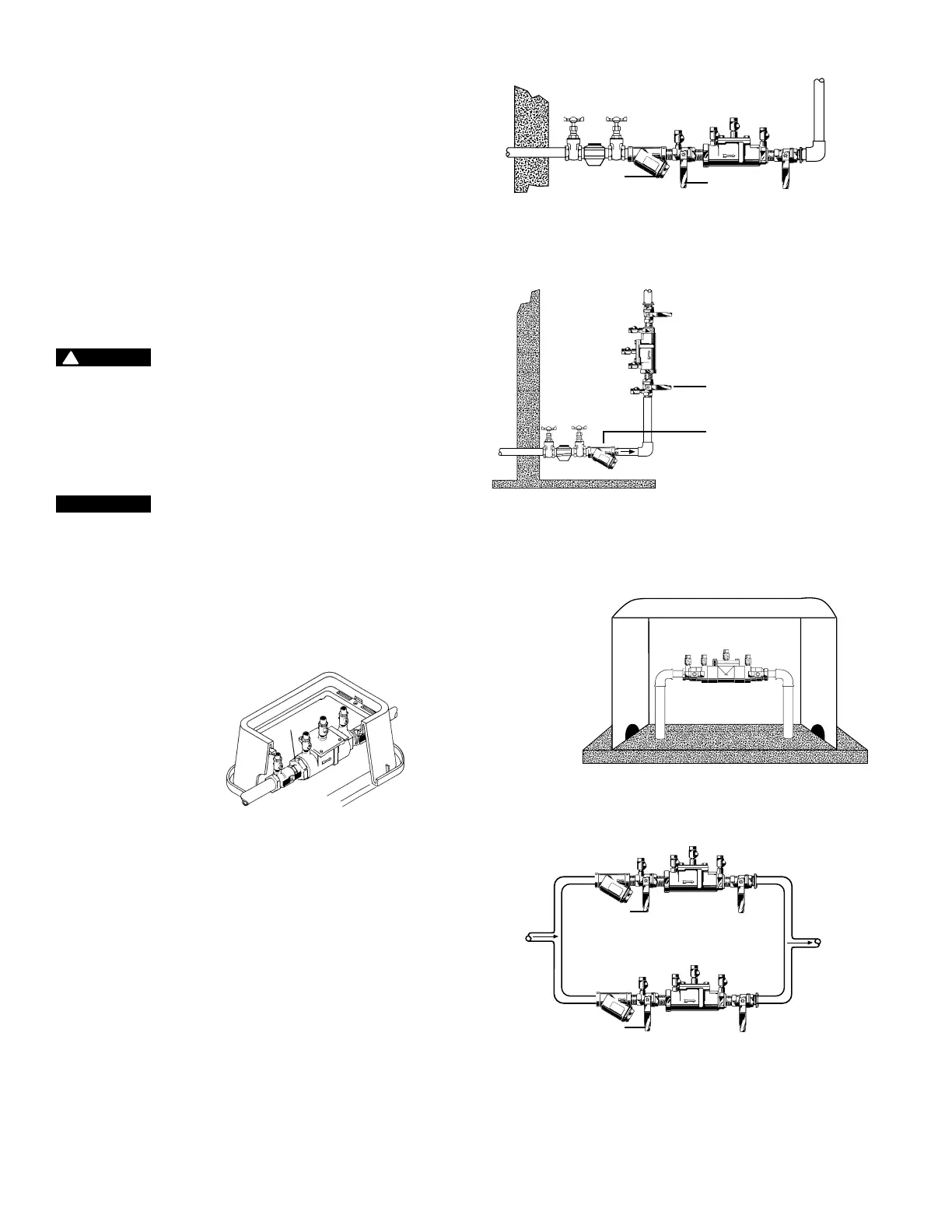
Check local codes for installation requirements. Pipelines should be
thoroughly flushed to remove foreign material before installing the
unit. A strainer should be installed ahead of the backflow preventer,
as shown in Figure 1, to prevent the disc from unnecessary fouling.
Install the valve inline with the arrow on valve body pointing in the
direction of flow.
For indoor installations, the valve must be easily accessible to
facilitate testing and servicing. The assembly can also be installed
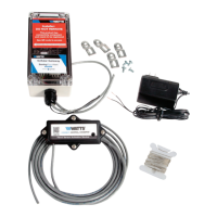
in a WattsBox insulated enclosure. (See Figure 2.) Do not install the
assembly in a concealed location.
CAUTION
!
Do not install a strainer when the backflow preventer is intended
for seldom-used water lines that are activated during emergencies,
such as fire sprinkler lines.
Series 007 and LF007 must be tested periodically in compliance
with local codes, but at least once a year or more often depending
upon system conditions. Regular inspection, testing, and cleaning
assure maximum life and proper product function.
NOTICE
Fire Protection System Installations. The National Fire
Protection Agency (NFPA) Guidelines require a confirming flow test
to be conducted whenever a “main line” valve such as a backflow
assembly or the shutoff valves have been operated. Certified testers
of backflow assemblies must conduct this test. The trim valves
of the detector meter bypass line, on assemblies so equipped,
should be shutoff during the confirming flow test. When the test is
completed, the trim valves must be returned to a fully open position.
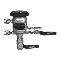
Meter Box Installation
First
Shutoff Valve
Strainer
007QT-S / LF007QT-S
WattsBox Insulated
Enclosure
Available in Aluminum
or Fiberglass.
For more information,
download ES-WB.
First
Shutoff Valve
First Shutoff Valve
Figure 1
Figure 3
First Shutoff
Valve
007QT-S/LF007QT-S
Vertical flow-up installation
Strainer
007QT-S / LF007QT-S
Figure 2
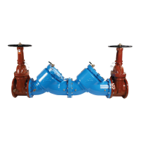
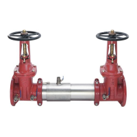
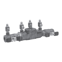
Parallel
Two or more Series 007 and LF007 smaller size valves may be
piped in parallel (where approved) to serve a larger supply pipe main
as shown in Figure 3. This type of installation is employed whenever
it is vital to maintain a continuous supply of water or where
interruptions for testing and servicing would be unacceptable. The
installation increases capacity where needed beyond that provided
by a single valve and permits testing or servicing of an individual
valve without shutting down the complete line.
For two valve installations the total capacity of the devices should
equal or exceed that required by the system.
The quantity of valves used in parallel should be determined by
the judgment of the compliance engineer, based on the operating
conditions of a specific installation.
 Loading...