5
e T-30 transfer switch installation is divided into 3 segments:
1. Incoming shore power
2. Incoming generator power
3. Power output to panel (distribution panel or power center)
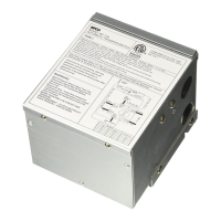
Remove the top cover with a Phillips screwdriver to expose the wiring box.
Note: All cables from Shore Cord, Generator and Control Panel routed to or from the T-30 Transfer
Switch should go through a strain relief (customer supplied) to keep cables from being pulled out of
the transfer switch enclosure.
To install the T-30 transfer switch follow the steps below:
Incoming Shore Power:
1. Connect the black wire from the shore cord to the black wire on transfer switch marked Shore.
2. Connect the white wire from the shore cord to the white wire on transfer switch marked Shore.
3. Connect the ground (copper) wire from the shore cord to the ground bar on transfer switch
marked equipment ground.
Incoming Generator Power:
4. Connect the black wire from the generator to the black wire on transfer switch marked Generator.
5. Connect the white wire from the generator to the white wire on transfer switch marked Generator.
6. Connect the ground (copper) wire from the shore cord to the ground bar on transfer switch
marked equipment ground.
Power Output to Panel:
7. Connect the black wire from the Distribution Panel to the black wire on transfer switch marked
Panel.
8. Connect the white wire from the Distribution Panel to the white wire on transfer switch marked
Panel.
9. Connect the ground (copper) wire from the Distribution Panel to the ground bar on transfer
switch marked equipment ground.
Final Assembly:
10. Slide the wiring box cover over the internal wire connections and tighten with one Phillips screw
in the center.
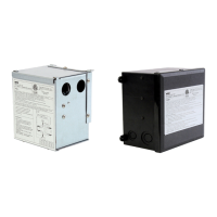
11. Install the two mounting brackets. For power center mounting, position the brackets so the
right-angle tabs face away from the from the enclosure and fasten with 2 screws on each side. Remove
the 2 screws from the top rear of the WF-8900 enclosure. Slide the T-30 as-sembly down over the
mounting rails on the WF-8900 enclosure and push down until the right-angle portion of the bracket
stops movement. Fasten the T-30 in place with the 2 screws removed earlier.
WallMounting (T-30WM Model): Place the brackets so that the small right-angle tabs face inward
and attach with 2 Phillips screws on each side. Fasten to the wall with 2 fasteners through each brack-
et (fasteners not supplied). Note: Fasteners must be able to safely support a 5 lb minimum load.
 Loading...