Choosing a Location for the Signal Meter
Installing the Spacer
3
2
1
Installing the Signal Meter
Modes
6
5
4
On the back of the wall
plate, there are four
labeled cables.
3 = Antenna
4 = Cable
5 = TV2
6 = TV1
Connect the cable coming from the antenna to the
ANT IN ( ) RF connection on the SensarPro signal meter.
Connect a cable from the TV to the TV1 ( ) RF connection,
and connect a cable from a second TV to the TV2 ( )
RF connection. (If more than two televisions are needed, a
splitter may be connected to TV2 to add televisions.) If your
RV is wired for Park Cable connection, connect that coaxial
cable to the Cable In ( ) RF connection.
Once the four cables have been attached, connect the 12
VDC power from the existing wall plate to the SensarPro
wall plate. The POWER should be connected to the post
marked “+” ( ) on the signal meter. The GROUND should
be connected to the post marked “−” ( ) on the SensarPro
signal meter. Input voltage must be between 9 and 16 VDC
with a maximum draw of 500 mA.
1 = Power
2 = Ground
With all of the cables connected, carefully feed the cables
back into the hole in the wall. Align the mounting holes on the
wall plate so that they form a line perpendicular to the floor.
If the spacer was installed, align the holes in the SensarPro
wall plate with the holes in the spacer.
Pre-drill mounting holes if this is a new installation. Insert two
of the provided mounting screws, and secure the SensarPro
signal meter to the wall.
Select a location for the
SensarPro signal meter.
Keep in mind that the
SensarPro signal meter
must be accessible, must
be connected to the
antenna, television, and
12 VDC power, and will
extend one inch into the
mounting surface.
Avoid installing the
SensarPro signal meter on
an exterior wall.
Once a location has been
selected, cut a 3.30” tall
by 1.87” wide section in the
wall for the signal meter.
See actual size template above. If unable to cut out the
tabs using the provided template, proceed to Installing the
Spacer. Otherwise, proceed to Installing the Signal Meter.
For Technical Services, call 1-800-788-4417
or email csvc@winegard.com.
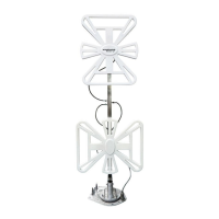
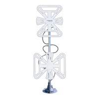
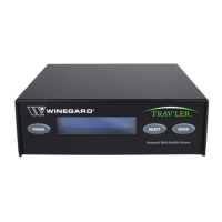
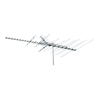
TV Signal
Strength Meter
If not using an outlet box or if unable to cut
out the tabs with the template, the spacer
may be needed. (The tabs in the template
are not needed when using the spacer.)
Place the spacer over the hole cut out for
the signal meter. Screw the spacer to the
wall with two mounting screws.
1 2
1.87”
3.30”
.14”
.12”
.25”
.25”
tab
Spacer
ANT IN
TV2
TV1
CABLE IN
3 4 5 6
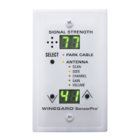
1 = Speaker
2 = Signal Strength
3 = Select Button
4 = Available Modes
5 = Up/Down Buttons
6 = Mode Display
The signal meter has two
main modes: PARK CABLE
and ANTENNA. The SELECT
button on the front of the
signal meter cycles through
all six modes (PARK CABLE
and five ANTENNA modes).
6
4
2
1
3
5
2452266