Home
Woodward
Control Unit
350108V2
Woodward 350108V2 User Manual
4
of 1
of 1 rating
242 pages
Give review
Manual
Specs
To Next Page
To Next Page
Loading...
Product Manual 35018V1
(Revision B, 2/2017)
Original Instructions
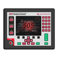
505XT Digital Control for Steam Turbines
(Single valve, Extraction and/or Admission)
8200-1310, 8200-1311, 8200-1312
Manual 35018 consists of 2 volumes (35018V1 & 35018V2)
Installation and Operation Manual Volume 1
2
Table of Contents
Default Chapter
3
Table of Contents
3
Warnings and Notices
8
Electrostatic Discharge Awareness
10
Regulatory Compliance
11
Chapter 1. General Information
16
Introduction
16
Controller Overview
16
Figure 1-1. Typical Single or Dual Inlet Steam Turbine
18
Figure 1-2. Typical Extraction And/Or Admission Steam Turbine
18
Functional Block Diagrams
19
Figure 1-3. Explanation of Symbols
20
Figure 1-4. Single or Split-Range Turbine Configurations
20
(Valve Demand Overview)
20
505 Inputs and Outputs
21
Figure 1-5. Turbine Configurations Using Extraction And/Or Admission
21
(Valve Demand Overview)
21
Table 1-2. Selectable Functions for Discrete Inputs
22
Table 1-3. Selectable Functions for 4-20Ma Analog Outputs
23
Table 1-4. Selectable Functions for Relay Output States
24
Optional Distributed I/O
25
Figure 1-6. Linknet Distributed I/O Node
25
Figure 1-7. Vibration Wizard for Linknet Node 1
26
Figure 1-8. Linknet Node 1 with 4 Vibration Signals
26
Figure 1-9. Vibration Monitoring Page
27
Keypad and Display
28
Figure 1-10. 505 Keypad and Display
28
Watchdog Timer/Cpu Fault Control
29
Chapter 2. Hardware Specifications
30
Flex505 Description and Features
30
Figure 2-1. Functional Block Diagram (505 Control)
30
Environmental Specifications
31
Maintenance Info and Recommendations
31
Electromagnetic Compatibility (EMC)
32
Outline Drawing for Installation
32
Figure 2-2. 505D Outline Drawing
33
Input Power Specification
34
Visual Indicators (Led's) & CPU Configuration
34
Communications (Ethernet)
35
Communications (CAN)
36
Table 2-3. CAN Specifications
37
Specifications
38
Communications (Service Ports)
39
Figure 2-3. COM1 Example RS-485 Wiring
39
Hardware - Terminal Blocks & Wiring
40
Figure 2-4. 505 Back Cover Label
40
Terminal Block Connectors
41
Hardware - Speed Sensor Inputs
41
Figure 2-5. Terminal Block Connectors
41
Figure 2-6. Speed Sensor Block Diagram
42
Hardware - Analog Inputs (4-20 Ma)
43
Figure 2-7. Analog Input - Self-Powered Block Diagram
43
Hardware - Analog Outputs (4-20 Ma)
44
Figure 2-8. Analog Input - Loop-Powered Block Diagram
44
Hardware - Actuator Outputs
45
Figure 2-9. Analog Output Block Diagram
45
Hardware - Discrete Inputs
46
Figure 2-10. Actuator Output Block Diagram
46
Figure 2-11. Discrete Input Block Diagram
46
Hardware - Relay Outputs
47
Figure 2-12. Relay Output Block Diagram
47
Troubleshooting Fault Codes
48
Troubleshooting & Commissioning Checks
48
Chapter 3. 505XT Control Description
51
Introduction
51
Turbine Start Modes
51
Start Permissive
52
Open Wire Detection on MPU Speed Signals
52
Zero Speed Signal Override
52
Figure 3-1. Open Wire Detection Test
52
Direction of Rotation Detection
53
Figure 3-2. Speed Input Channel - Phase Difference
53
Detecting Zero Speed
54
Manual Speed Override
54
Figure 3-3. Speed Probe Rotation Check
54
Figure 3-4. Speed Probe Zero Speed Detect
54
Automatic Speed Override
55
Acceleration Limiter
55
Turbine Start Mode Procedures
55
Figure 3-5. Manual Start Mode Example
56
Figure 3-6. Semiautomatic Start Mode Example
57
Figure 3-7. Automatic Start Mode Example
58
Figure 3-8. Idle/Rated Start
60
Figure 3-9. Automatic Start Sequence
61
Table 3-2. Hot and Cold Parameter Interpolation Rates and Delays
62
Table 3-3. All Required Conditions, if Configured, for a Warm or Hot Start
63
Speed Control Overview
65
Speed PID Operational Modes
66
Figure 3-10. Speed Control Functional Diagram
66
Figure 3-11. Speed PID Control Modes
68
Figure 3-12. Frequency and Unit Load Relationship
69
Figure 3-13. Speed Relationships
71
Table 3-4. Frequency Arm/Disarm Generator Control Modes
73
Figure 3-14. Load Sharing Logic
77
Manual Demand
78
Load Rejection
79
Feed-Forward Input
79
Cascade Control
81
Figure 3-15. Typical Anti-Surge Valve and Speed Feed-Forward Logic Trend
81
Figure 3-16. Cascade Functional Diagram
82
Auxiliary Control
86
Figure 3-17. Aux Control Overview
86
Remote Auxiliary Set Point
89
Extraction/Admission Control
91
Figure 3-18. Extraction/Admission Control Overview
91
Figure 3-19. Transitions between Speed Only and Ratio Limiter Control - Auto Mode
93
Figure 3-20. Transitions between Speed Only and Ratio Limiter Control - Manual
94
Figure 3-21. Extraction/Admission Control Panel
95
Steam Performance Map Menu
97
Figure 3-22. Typical Extraction Steam Map
100
Figure 3-23. Typical Admission Steam Map
102
Figure 3-24. Typical Extraction & Admission Steam Map
103
Table 3-7. Alternate Modes for Ext/Adm Turbines
104
Figure 3-32. Ext/Adm Mode Control Priorities
109
Inlet Steam Pressure Control
110
Figure 3-33. Configured for Full Decoupled Mode (no Map)
110
Exhaust Steam Pressure Control
111
Figure 3-34. Inlet Steam Pressure Control Overview
111
HP Valve Limiter
112
Figure 3-35. Exhaust Steam Pressure Control Overview
112
LP Valve Limiter
113
Manual Valve Demand
113
Inlet Steam Pressure Compensation
114
Isolated PID Control
114
Emergency Shutdown
115
Controlled Shutdown
116
Overspeed Test Function
117
Local/Remote Function
117
Table 3-8. Exceptions to Local Mode Contact Input and Modbus Command Disabled
118
Relays
119
Chapter 4. Configuration Procedures
121
Program Architecture
121
Display Modes and User Levels
121
Configuring the 505XT
122
Figure 4-1. Initial HOME Screen (Unit Not Configured)
122
Figure 4-2. Configuration Menu - Configuration Mode (Edit)
124
Exiting the Configure Mode
151
Table 4-3. Configuration Error Messages
152
Valve/Actuator Calibration & Test
159
Calibration/Stroking Procedure
159
Chapter 5. 505 Operation
161
Software Architecture
161
Power-Up Screen
161
Figure 5-1. Software Architecture
161
Figure 5-2. 505 Splash Screen
162
Figure 5-3. Boot-Up to HOME Screen
162
Control Mode Architecture
163
Figure 5-4. Control Mode Architecture
163
User Login Levels
164
Figure 5-5. Mode Screen
164
Navigation
165
Page Organization
165
Figure 5-6. Navigation Cross
165
Figure 5-7. Service Menu Showing "Speed Control" IN-Focus
165
Figure 5-8. Configuration Menu - Operation Mode (View Only)
166
Figure 5-9. Configuration Menu - Configuration Mode (Edit)
166
Overview Screen
167
Speed Control Screen
167
Figure 5-10. Overview Screen
167
Figure 5-11. Speed Control Screen
167
Valve Demand Screen
168
Figure 5-12. Valve Demand Screen
168
Controllers Screen
169
Cascade Control Screen
169
Figure 5-13. Controllers Screen
169
Figure 5-14. Cascade Control Screen
169
Auxiliary Control Screen
170
Inlet Control Screen
170
Figure 5-15. Auxiliary Control Screen
170
Figure 5-16. Inlet Steam Pressure Control Screen
170
Extraction/Admission Control Screen
171
Figure 5-17. Ext/Adm Pressure Control Screen
171
Exhaust Control Screen
172
Steam Map Screen
172
Figure 5-18. Exhaust Pressure Control Screen
172
Figure 5-19. Steam Map Screen
172
Analog Input Summary Screen
173
Figure 5-20. Steam Map - Mode Popup
173
Figure 5-21. Analog Input Summary Screen
173
Contact Input Summary Screen
174
Analog Output Summary Screen
174
Figure 5-22. Contact Input Summary Screen
174
Figure 5-23. Analog Output Summary Screen
174
Relay Output Summary Screen
175
Actuator Driver Summary Screen
175
Figure 5-24. Relay Output Summary Screen
175
Figure 5-25. Actuator Driver Summary Screen
175
Starting Procedures (Start Curve Screen)
176
Figure 5-26. HOME Menu Showing "Startup Curve" IN-Focus
176
Overspeed Test Function (Speed Control Screen)
177
Figure 5-27. Overspeed Test Permissives
177
Figure 5-28. Internal (505) Overspeed Test
178
Figure 5-29. External Overspeed Test
178
Stop Key
179
Alarm Summary
179
Figure 5-30. ALARM Screen
179
Table 5-1. ALARM Messages
180
Shutdown Summary
183
Figure 5-31. Shutdown Summary Screen
183
Manual Dynamic Adjustments of Speed, Cascade, Auxiliary, Inlet, Exhaust and Ext/Adm Controls
185
Figure 5-32. Speed Dynamics Adjustment Screen
185
Figure 5-33. Typical Response to Load Change
188
Figure 5-34. Overview of the Automated PID Optimizer Routine
189
Figure 5-35. Optimization Routine Overview Trend
190
Figure 5-36. Configuration Parameters 'Configure' Pop-Up
191
Chapter 6. Communications
198
Modbus Communications
198
Figure 6-1. ASCII/RTU Representation of 3
199
Table 6-2. Modbus Frame Definition
200
Port Adjustments
201
505 Control Modbus Addresses
201
Table 6-7. Boolean Write Addresses
202
Table 6-8. Boolean Read Addresses
203
Table 6-9. Analog Read Addresses
210
Table 6-10. Analog Write Addresses
215
Table 6-12. Analog Read Register (3:0234) Control Status
216
Table 6-14. Analog Read Register (3:0236) Map Limiter Status Messages
217
Table 6-17. Analog Output Configuration
218
Table 6-18. Relay Configuration – for Level Switches
219
Table 6-19. Relay Configuration – for State Indications
220
Table 6-20. Contact Input Configurations
221
Specific Address Information
222
Chapter 7. Product Support and Service Options
224
Product Support Options
224
Product Service Options
224
Returning Equipment for Repair
225
Replacement Parts
226
Engineering Services
226
Contacting Woodward's Support Organization
226
Technical Assistance
227
Appendix A. 505Xt Configuration Mode Worksheets
228
Revision History
239
D Eclarations
240
Other manuals for Woodward 350108V2
Product Manual
176 pages
4
Based on 1 rating
Ask a question
Give review
Questions and Answers:
Need help?
Do you have a question about the Woodward 350108V2 and is the answer not in the manual?
Ask a question
Woodward 350108V2 Specifications
General
Brand
Woodward
Model
350108V2
Category
Control Unit
Language
English
Related product manuals
Woodward easYgen-3000 Series
67 pages
Woodward DSLC
114 pages
Woodward easYgen
30 pages
Woodward 9907-175
12 pages
Woodward 9907-838
12 pages
Woodward 9907-252
36 pages
Woodward 8406-121
234 pages
Woodward QuickTrip
69 pages
Woodward 9905 Series
52 pages
Woodward easYgen-1000
201 pages
Woodward easYgen-1400
36 pages
Woodward easYgen-2000 Series
610 pages