Built-In Self-Test (BIST) Instructions
ZCU104 Evaluation Kit
2
www.xilinx.com
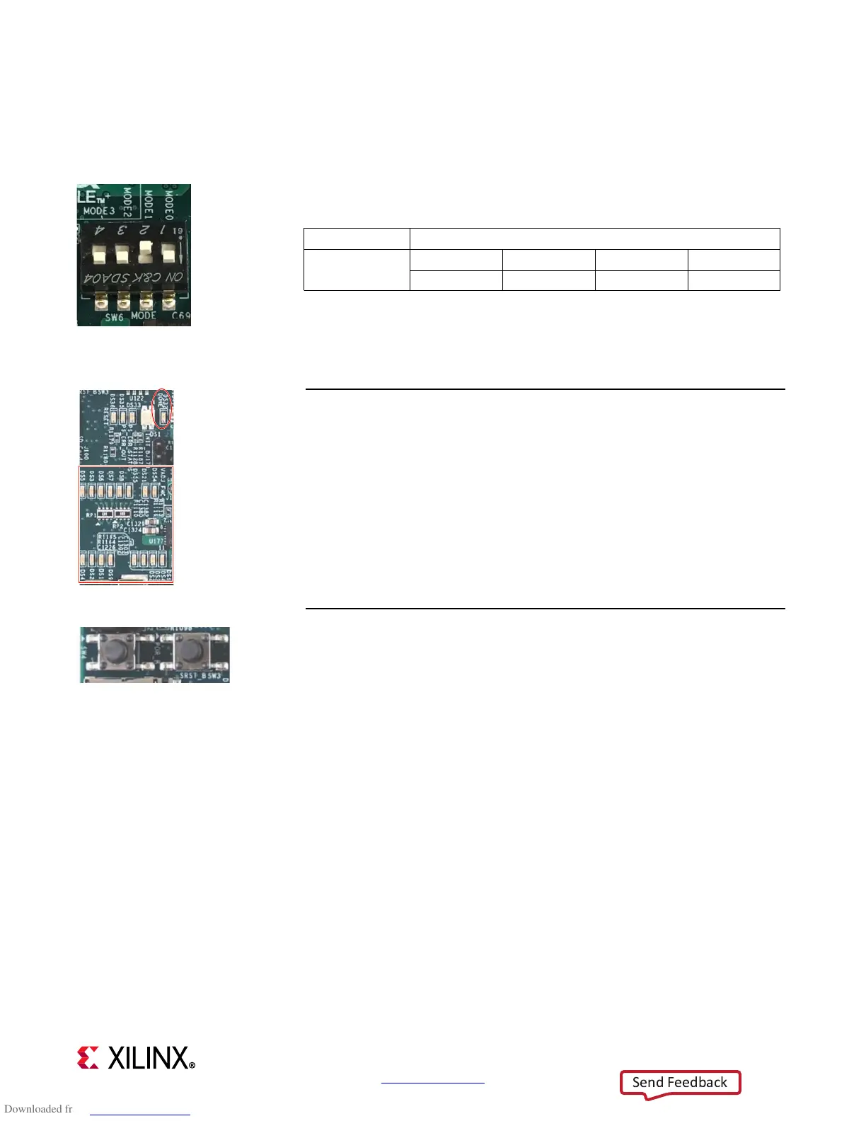
STEP 1: Set Configuration Switches
Set mode switch SW6 to QSPI32.
Note: For this DIP switch, in relation to the arrow, moving the switch
toward the label ON is a 0. DIP switch labels 1 through 4 are equivalent to
MODE pins 0 through 3. Set DIP switches labeled 1 to 4 to ON, OFF, ON,
ON.
STEP 2: Connect Power
Plug the power supply into a power outlet with one of the included power
cords.
Connect the 6-pin power supply plug to J52.
Turn on the board power with the SW1 slide switch.
If the two rows of Power Good LEDs glow green, the power system is good.
VADJ (DS8) will not be on.
If the DONE LED (DS32) circled here glows green, the Zynq UltraScale+ device
has configured successfully.
STEP 3: Initiate Configuration
The built-in self-test (BIST) starts shortly after power on.
Note: Pressing the POR_B (SW4) or the SRST_B (SW3) button causes the
DONE LED to go out, the device to configure again, and the BIST to
restart.
The PL GPIO LEDs flash on and off several times at the start of the BIST.
Boot Mode Mode Pins [0:3]
QSPI32
1234
0100

 Loading...


