18
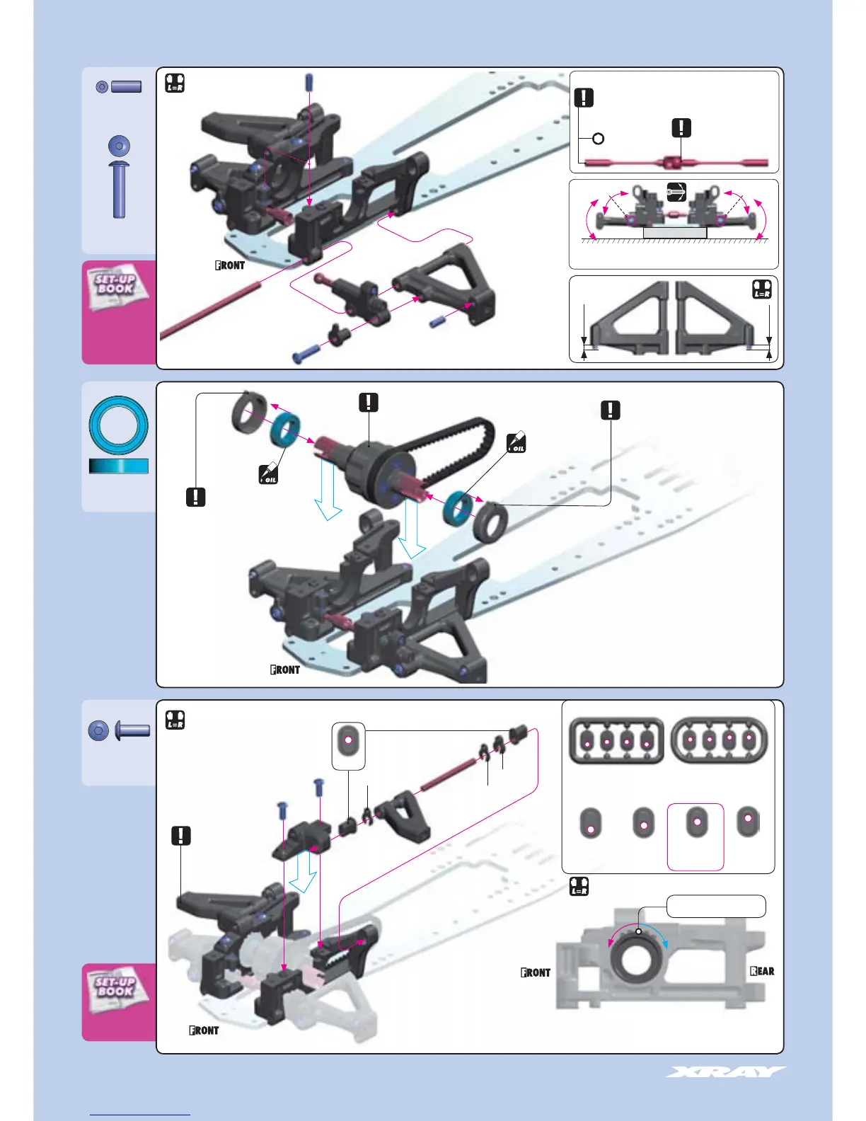
FRONT ROLL CENTER
ADJUSTMENT
FRONT ANTI-ROLL BAR
ADJUSTMENT
FRONT SUSPENSION
DOWNSTOP ADJUSTMENT
A
B
901308
SB M3x8
902314
SH M3x14
941016
BB 10x16x4
902308
SH M3x8
➊
➋
➌
➍
➎
➏
➐
➊
➊
➋
➋
➌
➊
➋
➌
➍
➎
➏
➐
➑
➑
NOTE
ORIENTATION
Both bushings must
be in same position
NOTE
ORIENTATION
Both bushings must
be in same position
NOTE
Left and right
arms are identical
Use (-0.5mm) suspension holders for initial assembly
FRONT ROLL CENTER INSERT POSITIONS
-1.5mm -0.5mm +0.5mm +1.5mm
+0.5mm
INITIAL POSITION
Place tab in this notch
FRONT BELT TENSION ADJUSMENT
TO TIGHTEN FRONT BELT
Rotate BOTH front composite
bushings in arrow direction (A)
TO LOOSEN FRONT BELT
Rotate BOTH front composite
bushings in arrow direction (B)
1mm
0.5mm
1.5mm
There are two different frames, rounded and square,
however both feature the same eccentric holders
NOTE
ORIENTATION
DETAIL
Ensure that the suspension arms move freely.
Ensure that the eccentric holders move freely.
Do not insert ball
into cup too deeply
or bars will bind
during operation
Each anti-roll bar blade has a hex hole at
its end. Use a 1.5mm hex wrench to adjust
the blades.
FRONT ANTI-ROLL BAR
STEP
➐
2.5mm
1.5mm
2.5mm
BEARING
OIL
BEARING
OIL
DETAIL
INITIAL
SETTING

 Loading...