These installation instructions provide essential information for installing VESDA-E VEU Aspirating Smoke Detectors in accordance with the system design. Additional installation and
product documentation is listed below in the Reference Documents section.
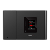
VESDA-E VEU Installation Instructions
System Components
The detector is shipped with the following components:
• 1 aspirating smoke detector
• 1 mounting bracket
• 1 mounting template for directly mounting the detector to the mounting surface
• 1 End of Line Resistor for the monitored GPI
• 1 installation instruction sheet
Prerequisites
• A completed system design.
• A 24V DC Power Supply, compliant with local codes and standards.
• Screws and inserts that are appropriate for the mounting suface.
• Type A to Type B USB Interface Lead for initial conguration of the detector.
• Labels as specied in the system design, e.g. Sampling Point labels
• Cable glands that are compliant with the IP rating of the detector.
• Conduit, as specied in the system design.
• 0.2 mm
2
to 2.5 mm
2
(24 - 14 AWG) wiring for relays.
• A PC or laptop installed with Xtralis VSC for initial conguration.
• Standard connection instructions for where the detectors are to be added to a corporate
network.
Standards Compliance
UL and ULC
For open area, open area high velocity and duct protection the re alarm threshold (setting)
that initiates an evacuation signal must be set such that the sensitivity of each sampling
hole is more sensitive than 10%/m (3.2 %/ft) as determined by the ASPIRE software.
European Installations
The product must use a power supply conforming to EN54: Part 4.
The product is compliant with EN 54-20 sensitivity requirements provided the following
conditions are met:
• For a Class A detector, hole sensitivity must be better than 1.5% obscuration/m and
transport time less than 70 seconds
• For a Class B detector, hole sensitivity must be better than 3% obscuration/m and
transport time less than 90 seconds
• For a Class C detector, hole sensitivity must be better than 10% obscuration/m and
transport time less than 110 seconds
These limits should be veried using ASPIRE during the design of the sampling pipe
network.
The product is compliant with EN 54-20 ow monitoring requirements provided the
following conditions are met:
• The minor low and minor high ow thresholds should be set at 85% and 115%
respectively
• The ow through the detector predicted by ASPIRE must be greater than 20 L/m.
Power Consumption (18 - 30 VDC Supply)
Quiescent In Alarm
Aspirator Speed Setting 1 Setting 5 Setting 10 Setting 1 Setting 5 Setting 10
VEU-A00 7.0 W 8.8 W 14.7 W 7.8 W 9.6 W 15.5 W
VEU-A10 8.2 W 10.0 W 15.8 W 10.4 W 11.6 W 16.6 W
Environmental Requirements
• Temperature
• Ambient: 0°C to 39°C (32°F to 102°F)
• Sampled Air: -20°C to 60°C (-4°F to 140°F)
• Tested to: -20°C to 55°C (-4°F to 131°F)
UL: -20°C to 50°C (-4°F to 122°F)
• Humidity: 10-95% RH, non-condensing
Note:
Please consult your Xtralis representative for information on operation outside
these parameters or where sampled air is continually above 0.05% obs/m
(0.015% obs/ft) under normal operating conditions.
Reference Documents
Additional installation and product information is contained in the following documents,
which are available for download in the Xtralis partner extranet at www.xtralis.com.
• 22061 - VESDA-E VEU-A00 Product Guide
• 22077 - VESDA-E VEU-A10 Product Guide
Installation Instructions
Notes
The VESDA-E detector can be mounted in an
upright or inverted position. Do not mount the
detector with a sideways orientation.
Ensure the mounting surface is at as this allows an
air tight seal to be achieved between the sampling
pipe and the tapered air inlet pipes on the detector.
Refer to the detector Product Guide for information
on inverted mounting.
A
B
Ensure that there is sufcient clearance to mount
the detector, noting the location of air sampling
pipes and cable entry points. Due to the rigid nature
of the plastic pipe, installation must provide for
sufcient movement in all pipework (air inlet, air
exhaust and cable pipes) to allow pipe ends to be
easily tted and removed.
• A: Minimum 50 mm (2 in.) below ceiling level.
• B: The detector can be mounted directly
against a wall or obstruction.
Attach the detector to the wall using the mounting bracket
Position the mounting bracket as specied by the system designer
E
F
B
D
A
C
D