OPERATING INSTRUCTION
FP-1030A
REGULATED
DC POWER
SUPPLY
IIITROIIUGTIOII
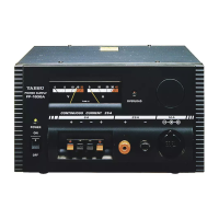
The Yaesu
FP-10304
is a high-quality,
Regulated DC
Power
Supply specifically
designed for
use with DC
pow-
ered radio
equipment. The FP-'l0304
provides
13.8
Volts
DC
at up
to
25 Amps
(continuous
duty).
Please
read
these operating instructions
thoroughly
so
as to ensure
proper
installation
and utilization
of this
unit.
We recommend
that these instructions
be kept
perma-
nently for
your
future
reference.
Features
[f
Overload Protection
A
current foldback
circuit
is utilized
to
prevent
dam-
age
to the unit
from
excessive
current
drain. An
"Over-
load" indicator
becomes
illuminated
when
an over-
load
condition
exists.
Note:
Should
the overload
protection
circuitry
be ac-
tivated,
switch off the
power
supply
and disconnect
the
external equipment immediately.
Extended
operation
under overload conditions
may
eventually
cause damage
to the
power
supply.
f
High
RFI lmmunity
The FP-1030,4
is specifically
designed
for use
with
radio
communication
equipment.
It
therefore includes
extensive filtering
to
provide
high
immunity
from
erratic operation
which
might
be
caused
by Radio Frequency interference (RFl).
ll
Multiple DC
Output
connections
Besides
the two
pairs
of
(64)
snap-in DC
connec-
tions
and the
(25A)
screw-on DC
output
terminal,
the
FP-10304
features
a cigar-lighter
type DC
output
jack
for radio
equipment
equipped with
a hatching
cigar-
lighter
plug.
Note:
Do not
attempt to use
a cigar lighter in
this DC
output
port,
as
it is not
designed for
this
application,
and damage
to
the
power
supply may result.
VERTEX
STANDARD
CO.,
LTD.
4-8-8 Nakameguro,
Meguro-Ku, Tokyo 153-8644,
Japan
VERTEX
STANDARD
fr?lff,*H:rfi-,,'n'
i.*"'1,', ;,.1', 1..,
uu, . o
YAESU
EUROPE B.V.
P.O. Box 75525 11 18
ZN Schiphol. The
Netherlands
YAESU
UK LTD.
Unit
12,
Sun Valley Business Park,
Winnall
Close
Winchester, Hampshire,
SO23
0LB,
U.K.
YAESU
GERMANY
GmbH
Am Kronberger Hang 2,
D-65824
Schwalbach, Germany
VERTEX
STANDARD HK LTD.
Unit
5,
20lF
,
Seaview Centre,
139-141
Hoi Bun Road
lnstallation IiRs
Like
any electronic apparatus,
the
FP-l0304
should be
installed
in a location which
allows
free
air
circulation,
so
as to
provide
efficient cooling
for
the
power
supply
cir-
cuitry, The FP-103OAsfiould
not be installed
in locations
exposed to moisture,
as a significant electric
shock haz-
ard
will
exist.
We
recommend
that this unit not
be
installed
in extremely
hot, dusty,
or humid locations,
nor
in
areas
exposed
to
direct
sunshine.
Gonnections
and 0lelation
t
Confirm
that the
AC voltage
as
indicated
on
the
rear
panel
label
matches
the
AC
mains voltage in
your
area.
fl
Connect
a
good
earth
ground
to the GND terminal
on
the bottom
case, using a heavy,
braided
cable
for
con-
nection
to
your
main
station
ground
system.
t
Be
sure the FP-'1030A is
turned OFF,
then
plug
the
AC
cable into
your
station's wall outlet.
t
Confirm the
expected current drain for
the radio(s)
to
be
connected to the FP-1030,4.
The two
pairs
of snap-
in
terminals can only handle
a combined current
of 6
Amps,
while
the
screw-on
terminal can
provide
up to
25 Amps.
t
Connect each radio's Negative
(usually
Black) DC
cable to the
appropriate
Black
(-)
terminal
on the FP-
1030A,
and connect
each
radio's
Positive
(usually
Red)
DC
cable to the appropriate Red
(+)
terminal.
f
Turn
the
FP-10304
ON first,
then turn on
the
radio(s)
connected
to the
power
supply, Operation may
now
com mence.
[f
When
operation
is
completed,
turn the radio
(s)
OFF
first,
then
turn off the
power
supply.
A
Gaution
t
Do not Exceed
the
total
current
rating
for
this
power
supply. This
unit is designed
to
provide
a
maximum
aggregate
current
of
25 Amps
(total
of all output
ter-
minals),
Also,
do
not
exceed
a total current;
drain
of 6
Amps
(combined)
from
the two
pairs
of snap-in
out-
put
terminals.
t
Do not
use this
power
supply for
any
purpose
other
than
powering
radio
communication
equipment.
lt is
not
designed for
other
purposes
such
as battery
charging,
cigarette lighting,
powering
of motorized
equipment,
nor for lamps
(other
than
the
incidental
lamps inside
radio
equipment).
f
lf
the
AC
input fuse
should blow determine
the cause
of the failure
before
replacing
the fuse. When replac-
ing fuses,
use
only the specified
size
for
the
AC
volt-
age
in
use.