4.
The supplied power cable may be plugged
directly into the vehicle's cigarette lighter
receptacle, for casual use. For permanent
installation, the lighter plug may be removed,
and the leads routed directly to the battery
(red to positive, black to negative or ground).
Alternatively, the power leads may be routed
to the nearest power terminal, e.g. ignition
switch, fuse block, etc. If it is necessary to
extend the power leads, use the shortest
length possible, and use only #16 AWG in-
sulated copper wire (or larger) to avoid
excessive voltage drop.
CAUTION
BEFORE CONNECTING THE POWER CON-
NECTOR TO THE TRANSCEIVER, CHECK
THE BATTERY VOLTAGE WITH THE ENGINE
RUNNING (BATTERY CHARGING). IF THE
VOLTAGE EXCEEDS 15 VOLTS DC, THE
VEHICLE VOLTAGE REGULATOR SHOULD
BE ADJUSTED TO PROVIDE A MAXIMUM
CHARGING RATE OF LESS THAN 15 VOLTS
DC. ALSO, BE CERTAIN TO OBSERVE PROPER
POLARITY WHEN MAKING BATTERY CON-
NECTIONS. THE RED LEAD IS CONNECTED
TO THE POSITIVE BATTERY TERMINAL,
WHILE THE BLACK LEAD IS CONNECTED TO
THE NEGATIVE TERMINAL. REVERSED
POLARITY WILL NOT DAMAGE THE FT-
227RA, BECAUSE OF THE PROTECTIVE
CIRCUITRY INCORPORATED; HOWEVER,
THE TRANSCEIVER WILL NOT OPERATE
UNDER THESE CONDITIONS.
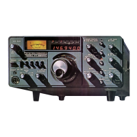
5.
Connect the power cable to the POWER
receptacle on the rear panel of the transceiver.
6.
Connect the 50 ohm antenna cable to the
ANT receptacle on the rear apron of the
transceiver.
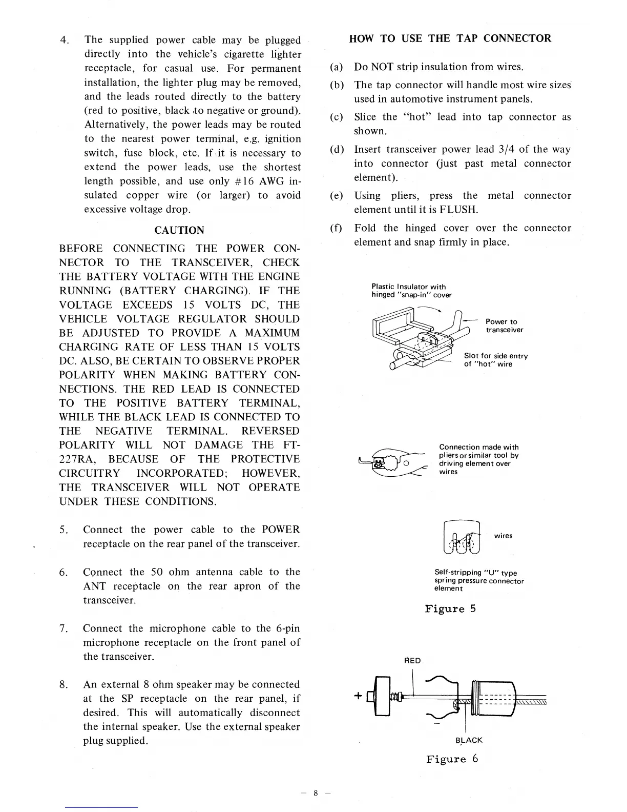
HOW TO USE THE TAP CONNECTOR
(a)
Do NOT strip insulation from wires.
(b)
The tap connector will handle most wire sizes
used in automotive instrument panels.
(c)
Slice the "hot" lead into tap connector as
shown.
(d)
Insert transceiver power lead 3/4 of the way
into connector (just past metal connector
element).
(e)
Using pliers, press the metal connector
element until it is FLUSH.
(f)
Fold the hinged cover over the connector
element and snap firmly in place.
Plastic Insulator with
hinged "snap-in" cover
Lft
° 45 g3t* ------ Power to
transceiver
•
Slot for side entry
41*
of "hot" wire
Connection made with
pliers or similar tool by
driving element over
wires
Self-stripping "U" type
spring pressure connector
element
wires
Figure 5
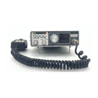
7.
Connect the microphone cable to the 6-pin
microphone receptacle on the front panel of
the transceiver.
RED
8.
An external 8 ohm speaker may be connected
at the SP receptacle on the rear panel, if
desired. This will automatically disconnect
the internal speaker. Use the external speaker
plug supplied.
BLACK
Figure
6
8
 Loading...