ELECTRICAL COMPONENTS
8-143
2. Check:
• Steering damper solenoid resistance
Out of specification → Replace the steer-
ing damper assembly.
▼▼▼▼▼▼▼▼▼▼▼▼▼▼▼▼▼▼▼▼▼▼▼▼▼▼▼▼▼▼
a. Disconnect the steering damper lead cou-
pler from wire harness.
b. Connect the pocket tester (Ω × 1) to the
steering damper lead coupler.
c. Measure the steering damper solenoid
resistance.
▲▲▲▲▲▲▲▲▲▲▲▲▲▲▲▲▲▲▲▲▲▲▲▲▲▲▲▲▲▲
EAS14B1055
CHECKING THE GEAR POSITION SENSOR
1. Remove:
• Fuel tank
Refer to “FUEL TANK” on page 7-1.
• Gear position sensor
Refer to “CRANKCASE” on page 5-71.
2. Check:
• Gear position sensor
Out of specification → Replace the gear
position sensor.
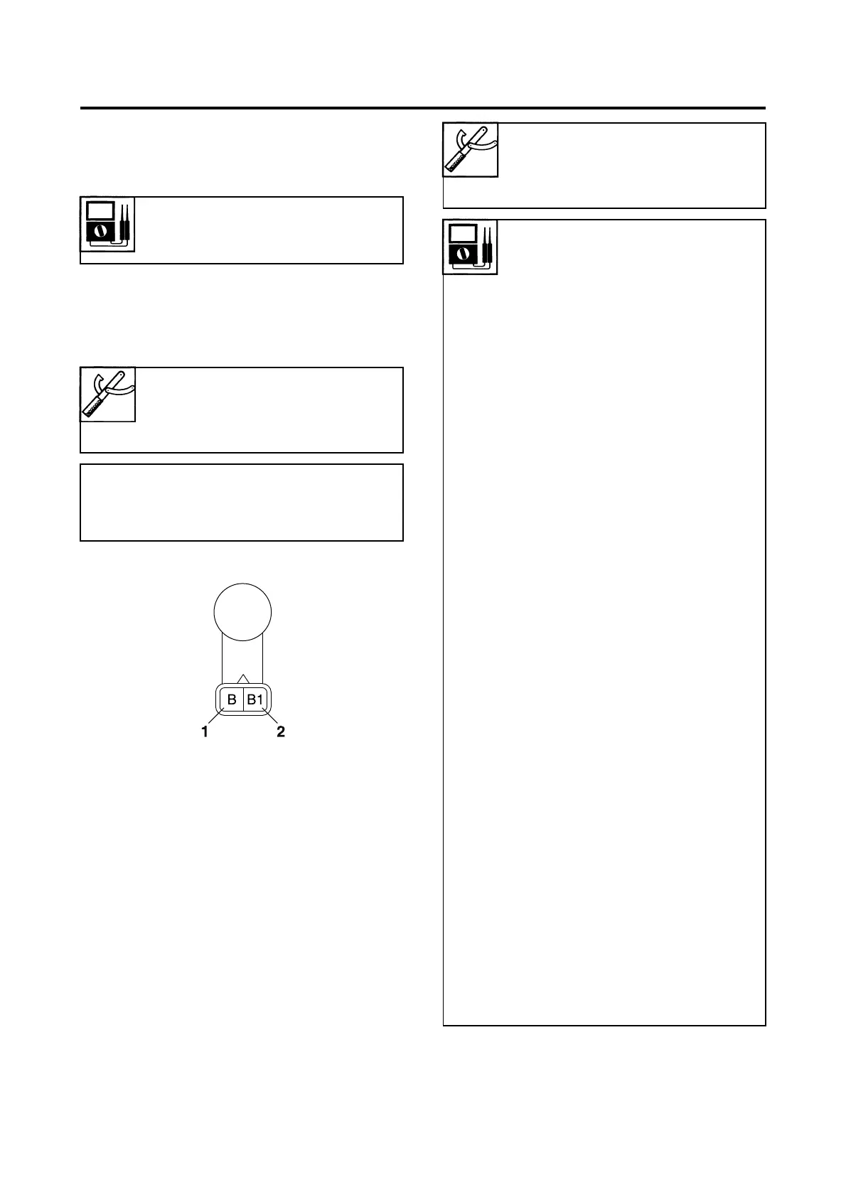
Steering damper solenoid resis-
tance
49.82–56.18 Ω at 20 °C (68 °F)
Pocket tester
90890-03112
Analog pocket tester
YU-03112-C
• Positive tester probe
Black “1”
• Negative tester probe
Black “2”
Pocket tester
90890-03112
Analog pocket tester
YU-03112-C
Result
Neutral position
Continuity
Positive tester probe
Sky blue “1”
Negative tester probe
Sensor terminal “a”
1st position
Continuity
Positive tester probe
White “2”
Negative tester probe
Sensor terminal “b”
2nd position
Continuity
Positive tester probe
Pink “3”
Negative tester probe
Sensor terminal “c”
3rd position
Continuity
Positive tester probe
Yellow/White “4”
Negative tester probe
Sensor terminal “d”
4th position
Continuity
Positive tester probe
White/Red “5”
Negative tester probe
Sensor terminal “e”
5th position
Continuity
Positive tester probe
Orange “6”
Negative tester probe
Sensor terminal “f”
6th position
Continuity
Positive tester probe
Gray “7”
Negative tester probe
Sensor terminal “g”

 Loading...