ELECTRICAL COMPONENTS
8-135
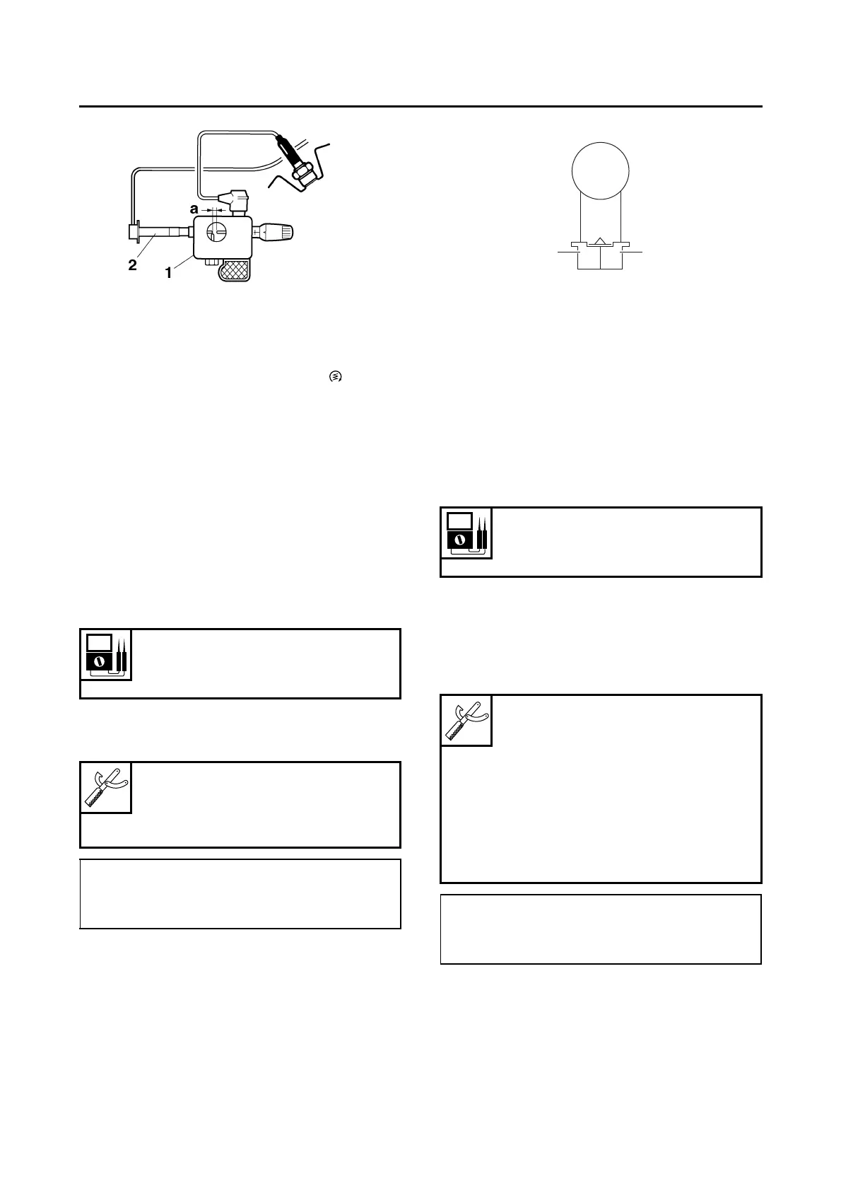
c. Turn the main switch to “ON”.
d. Measure the ignition spark gap “a”.
e. Crank the engine by pushing the “ ” side of
the start/engine stop switch and gradually in-
crease the spark gap until a misfire occurs.
▲▲▲▲ ▲ ▲▲▲▲▲▲▲▲▲ ▲ ▲▲▲▲ ▲ ▲▲▲▲ ▲ ▲▲▲▲▲▲▲
EAS30560
CHECKING THE CRANKSHAFT POSITION
SENSOR
1. Disconnect:
• Crankshaft position sensor coupler
(from the wire harness)
2. Check:
• Crankshaft position sensor resistance
Out of specification → Replace the crank-
shaft position sensor.
▼▼▼▼ ▼ ▼▼▼▼▼▼▼▼▼ ▼ ▼▼▼▼ ▼ ▼▼▼▼ ▼ ▼▼▼▼▼▼▼
a. Connect the pocket tester (Ω × 100) to the
crankshaft position sensor coupler as shown.
b. Measure the crankshaft position sensor re-
sistance.
▲▲▲▲ ▲ ▲▲▲▲▲▲▲▲▲ ▲ ▲▲▲▲ ▲ ▲▲▲▲ ▲ ▲▲▲▲ ▲▲▲
EAS30561
CHECKING THE LEAN ANGLE SENSOR
1. Remove:
• Lean angle sensor
(from the battery box.)
2. Check:
• Lean angle sensor output voltage
Out of specification → Replace.
▼▼▼▼ ▼ ▼▼▼▼▼▼▼▼▼ ▼ ▼▼▼▼ ▼ ▼▼▼▼ ▼ ▼▼▼▼ ▼▼▼
a. Connect the test harness– lean angle sensor
(6P) “1” to the lean angle sensor and wire
harness as shown.
b. Connect the pocket tester (DC 20 V) to the
test harness– lean angle sensor (6P).
2. Ignition coil
Crankshaft position sensor resis-
tance
228–342 Ω
Pocket tester
90890-03112
Analog pocket tester
YU-03112-C
• Positive tester probe
Gray “1”
• Negative tester probe
Black “2”
Lean angle sensor output voltage
Less than 65°: 0.4–1.4 V
More than 65°: 3.7–4.4 V
Pocket tester
90890-03112
Analog pocket tester
YU-03112-C
Test harness– lean angle sensor
(6P)
90890-03209
Test harness– lean angle sensor
(6P)
YU-03209
• Positive tester probe
Yellow/green (wire harness color)
• Negative tester probe
Black/blue (wire harness color)

 Loading...