MON/CUE function
216 PM5D/PM5D-RH Owner’s Manual Reference section
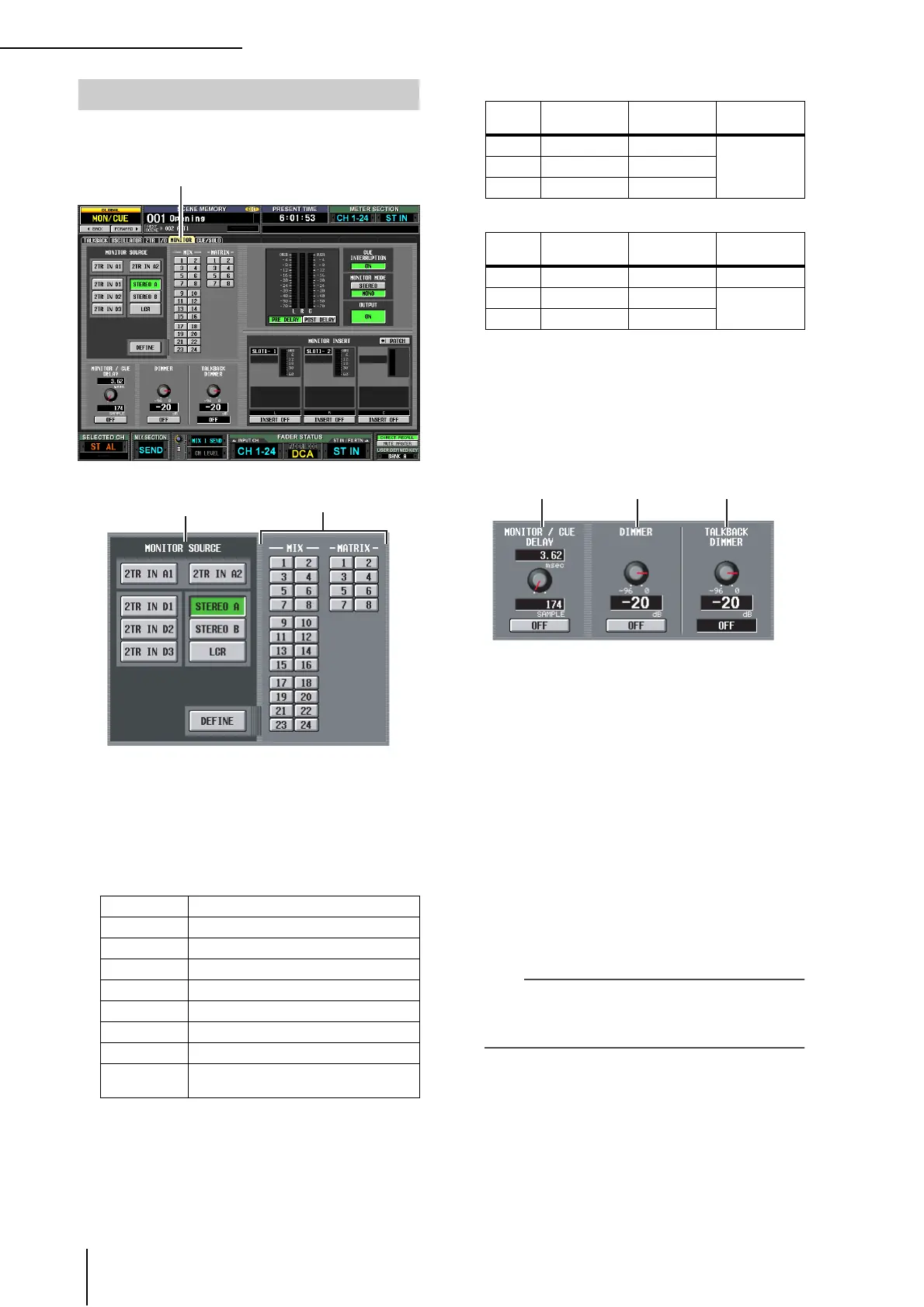
Here you can make settings and perform operations
related to monitoring.
A MONITOR SOURCE
Selects the source that will be monitored from the L/R/
C MONITOR OUT jacks. You can select one from 2TR
IN A1/A2, 2TR IN D1–D3, or DEFINE, and also simul-
taneously select one from STEREO A/B or LCR. These
buttons are linked with the various keys of the MONI-
TOR section in the top panel.
If a monitor source indicated by (*) is selected, the sig-
nal that is output will change depending on whether
the USE AS STEREO BUS button or the USE AS CEN-
TER BUS button is turned on in the STEREO B section
of the MIXER SETUP screen (➥ p.201).
❏ If the USE AS STEREO BUS button is on
❏ If the USE AS CENTER BUS button is on
B DEFINE
If “DEFINE” is selected in the MONITOR SOURCE
section, you can choose the signal that will be moni-
tored from the following.
MIX 1–24 . . . . . . . . MIX bus 1–24 output signal
MATRIX 1–8. . . . . . MATRIX bus 1–8 output signal
C MONITOR / CUE DELAY
Here you can make settings for the delay function pro-
vided on the MONITOR/CUE bus output. Use the
knob to specify the delay time (0–1000 msec), and use
the ON/OFF button to switch the delay on/off. If the
ON/OFF button is on, the monitor signal and cue sig-
nal will be delayed by the specified time. The delay time
units can be changed in the DELAY SCALE field found
in each screen of the INPUT DELAY/OUTPUT
DELAY function.
D DIMMER
When you turn this button on, the level of the signal
being monitored will be temporarily attenuated. The
knob adjusts the amount of attenuation that will occur
when the button is on. The range of adjustment is
–96 dB to 0 dB. While this button is on, the DIMM
indicator will appear in the upper right of the display.
Hint
You can also use an external switch connected to the GPI IN
connector to switch the dimmer on/off. To do so, assign the
MONITOR DIMMER ON function to the GPI IN port to which
the switch is connected. (
➥
p.177).
E TALKBACK DIMMER
This adjusts the amount by which the monitor signal
will be attenuated when talkback is on. The range of
adjustment is –96 dB to 0 dB. The talkback on/off sta-
tus is shown in the box below.
2TR IN A1 2TR IN ANALOG jack 1 input signal
2TR IN A2 2TR IN ANALOG jack 2 input signal
2TR IN D1 2TR IN DIGITAL jack 1 input signal
2TR IN D2 2TR IN DIGITAL jack 2 input signal
2TR IN D3 2TR IN DIGITAL jack 3 input signal
STEREO A STEREO A channel output signal (*)
STEREO B STEREO B channel output signal (*)
LCR LCR channel output signal (*)
DEFINE
The signal selected in the DEFINE section
(
2
) of this screen
MONITOR screen
MONITOR
1
Monitor
source
LRC
ST A STEREO A L STEREO A R
—ST B STEREO B L STEREO B R
LCR — —
Monitor
source
LRC
ST A STEREO A L STEREO A R —
ST B — —
STEREO B L
LCR STEREO A L STEREO A R
 Loading...