VIII. ENGINE ADJUSTMENTS
This chapter will discuss those places which
re
For detailed servicing and adjustments of indi-
quire adjustment after the engine has been assem- vidual components, refer to Chapter
V.
bled.
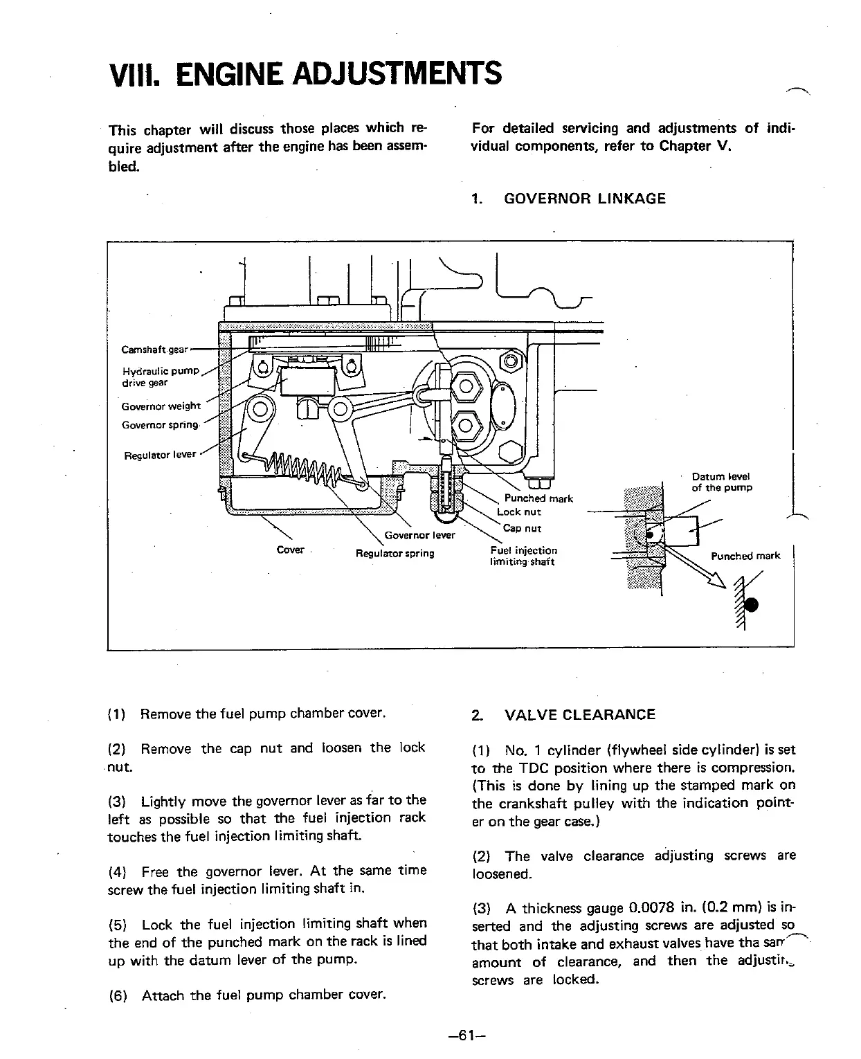
1.
GOVERNOR LINKAGE
Governor
weight
Governor
spring.
limitingghaft
(1)
Remove the fuel pump chamber cover.
(2)
Remove the cap nut and loosen the lock
nut.
(3)
Lightly move the governor lever as far to the
left as possible so that the fuel injection rack
touches the fuel injection limiting shaft.
(4)
Free the governor lever. At the same time
screw the fuel injection limiting shaft in.
(5)
Lock the fuel injection limiting shaft when
the end of the punched mark on the rack
is
lined
up with the datum lever of the pump.
(6)
Attach the fuel pump chamber cover.
2.
VALVE CLEARANCE
(1)
No. 1
cylinder (flywheel side cylinder)
is
set
to the
TDC
position where there
is
compression.
(This is done
by
lining up the stamped mark on
the crankshaft pulley with the indication point-
er on the gear case.)
(2) The valve clearance adjusting screws are
loosened.
(3) A thickness gauge 0.0078 in. (0.2 mm)
is
in-
serted and the adjusting screws are adjusted so
that both intake and exhaust valves have tha
sann
amount of clearance, and then the adjustir.,
screws are locked.
 Loading...