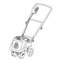
ADJUSTABLE TINE ASSEMBLY INSTRUCTION
Tines are identified (A,B,C,D) with letters stamped into the Tine Hubs.
CHANGE FROM FOUR TINES TO TWO TINES
Lift the Lock Pin rings and remove Lock Pins at
both ends of the shaft. Remove Tine A and D
from the shaft. (Fig. 3)
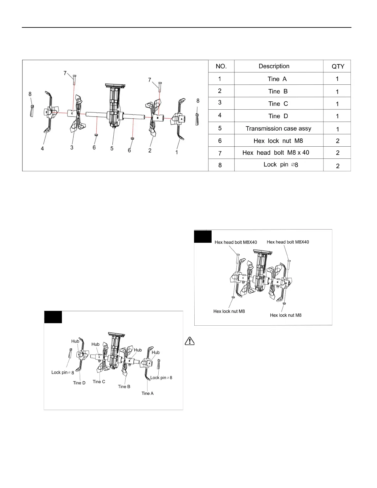
CHANGE FROM TWO TINES TO FOUR TINES
Install Tine A and D onto the shaft as shown.
Ensure holes in Tine Hubs and shaft are aligned.
Insert Lock Pin into the through holes and pull
Lock pin ring downward to lock the Pin into place.
Be sure to install Tines as shown in Fig 3. Tines
cannot be secured if assembled in other
sequence of Tine position. (Fig. 3)
In the event the lock Pins are lost or misplaced,
Tines A and D may be secured using the extra
M8X40 Hex head bolts and M8 Lock nuts
provided. (Fig. 4)
3
4
WARNING: Before adjusting tine assembly,
disconnect power supply. Failure to heed this
warning could result in serious personal injury.
7
Model TC70010-1
 Loading...