15 European Standards
YASKAWA TOEPC71061723A YASKAWA AC Drive CR700 Quick Start Guide 79
*1 Connect peripheral options to terminals -, +1, +2, B1, and B2. Do not connect an AC power supply lines to these terminals.
*2 For circuit protection, the main circuit is separated from the surface case that would otherwise come into contact with the main
circuit.
*3 The control circuit is a Safety Extra-Low Voltage circuit that must be separated from other circuits by reinforced insulation. Ensure
that the Safety Extra-Low Voltage circuit is connected as required.
*4 Reinforced insulation separates the output terminals from other circuits. Users may also connect circuits that are not Safety Extra-
Low Voltage circuits if the drive output is 250 Vac 1 A max. or 30 Vdc 1 A max.
■ Wire Gauges and Tightening Torques
Note:
• The recommended wire gauges based on drive continuous current ratings using 75 °C (167 °F) 600 V class 2 heat resistant indoor PVC
wire. Assume the following usage conditions:
–Ambient temperature: 40 °C (104 °F) or lower
–Wiring distance: 100 m (3281 ft.) or shorter
–Rated current value
• Use terminals +1, +2, +3, -, B1, and B2 to connect peripheral options such as a DC reactor or a braking resistor. Do not connect
anything other than optional devices.
• Refer to the specific instruction manual of each device for wire gauges when connecting peripheral devices or options to terminals +1,
+2, +3, -, B1, and B2. Contact Yaskawa or your nearest sales representative if the recommended wire gauges for the peripheral devices
or options are out of the range of the applicable gauge for the drive.
Three-Phase 200 V Class
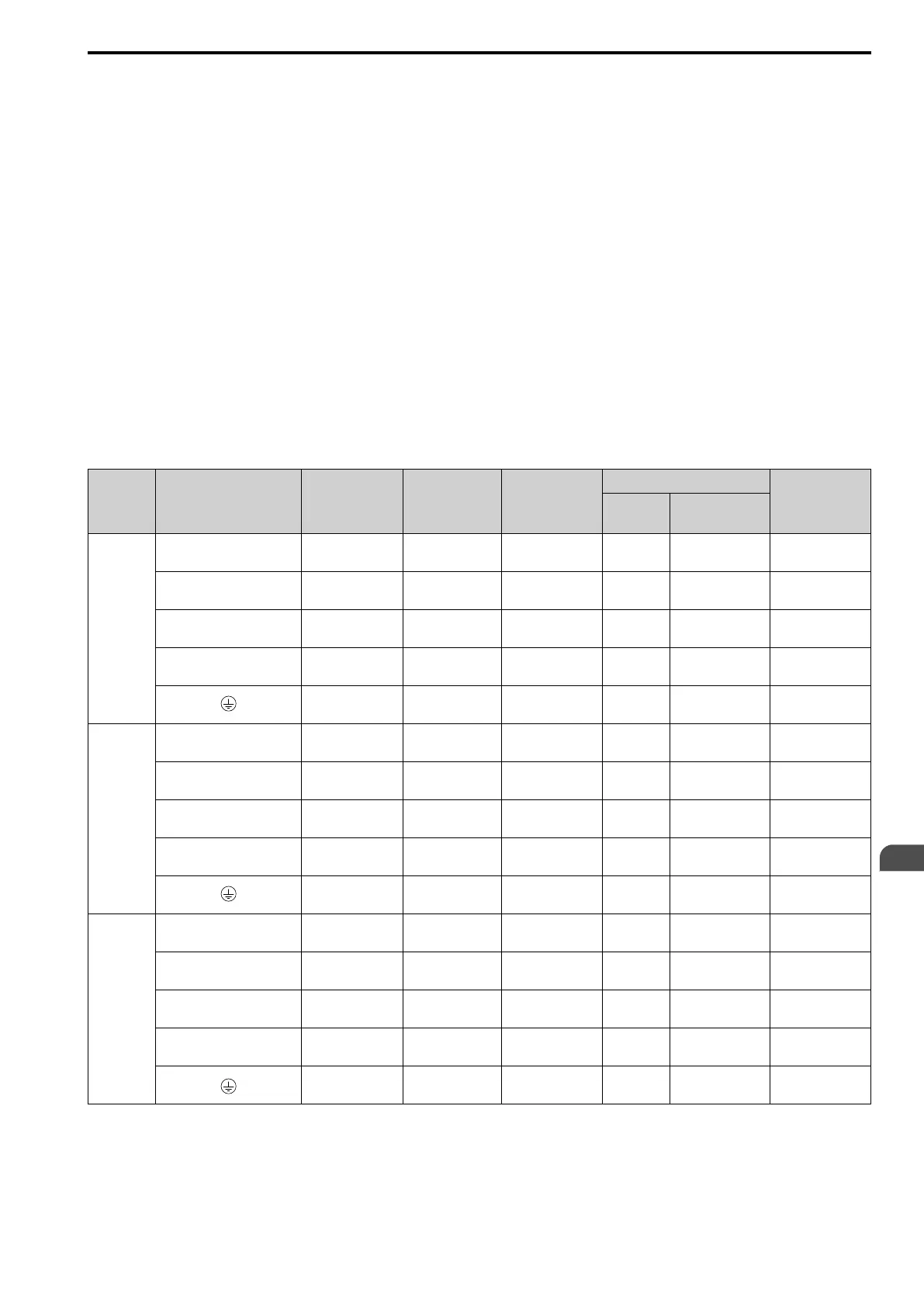
Table 15.2 Main Circuit Wire Gauges and Tightening Torques (200 V Class)
Model Terminal
Recomm. Gauge
mm
2
Applicable Gauge
(IP20 Applicable
Gauge
*1
)
mm
2
Wire Stripping
Length
*2
mm
Terminal Screw
Tightening
Torque
N∙m (lbf∙in)
Size Shape
2003
R/L1, S/L2, T/L3 2.5
2.5 - 10
(2.5 - 10)
10 M4 Slotted (-)
1.5 - 1.7
(13.5 - 15)
U/T1, V/T2, W/T3 2.5
2.5 - 10
(2.5 - 10)
10 M4 Slotted (-)
1.5 - 1.7
(13.5 - 15)
-, +1, +2 2.5
2.5 - 16
(2.5 - 16)
18 M5 Slotted (-)
2.3 - 2.5
(19.8 - 22)
*3
B1, B2 2.5
2.5 - 4
(2.5 - 4)
10 M4 Slotted (-)
1.5 - 1.7
(13.5 - 15)
2.5
*4
2.5 - 10
(-)
- M4
Phillips/slotted
combo
1.2 - 1.5
(10.6 - 13.3)
2005
R/L1, S/L2, T/L3 2.5
2.5 - 10
(2.5 - 10)
10 M4 Slotted (-)
1.5 - 1.7
(13.5 - 15)
U/T1, V/T2, W/T3 2.5
2.5 - 10
(2.5 - 10)
10 M4 Slotted (-)
1.5 - 1.7
(13.5 - 15)
-, +1, +2 2.5
2.5 - 16
(2.5 - 16)
18 M5 Slotted (-)
2.3 - 2.5
(19.8 - 22)
*3
B1, B2 2.5
2.5 - 4
(2.5 - 4)
10 M4 Slotted (-)
1.5 - 1.7
(13.5 - 15)
2.5
*4
2.5 - 10
(-)
- M4
Phillips/slotted
combo
1.2 - 1.5
(10.6 - 13.3)
2008
R/L1, S/L2, T/L3 2.5
2.5 - 10
(2.5 - 10)
10 M4 Slotted (-)
1.5 - 1.7
(13.5 - 15)
U/T1, V/T2, W/T3 2.5
2.5 - 10
(2.5 - 10)
10 M4 Slotted (-)
1.5 - 1.7
(13.5 - 15)
-, +1, +2 2.5
2.5 - 16
(2.5 - 16)
18 M5 Slotted (-)
2.3 - 2.5
(19.8 - 22)
*3
B1, B2 2.5
2.5 - 4
(2.5 - 4)
10 M4 Slotted (-)
1.5 - 1.7
(13.5 - 15)
2.5
*4
2.5 - 10
(-)
- M4
Phillips/slotted
combo
1.2 - 1.5
(10.6 - 13.3)
EN
 Loading...


