15 UL Standards
178 YASKAWA TOEPC71061752B GA500 Drive Installation & Primary Operation
◆ Low Voltage Wiring for Control Circuit Terminals
You must provide low voltage wiring as specified by the National Electric Code (NEC), the
Canadian Electric Code, Part I (CEC), and local codes. Yaskawa recommends the NEC class 1
circuit conductor. Use the UL approved class 2 power supply for external power supply.
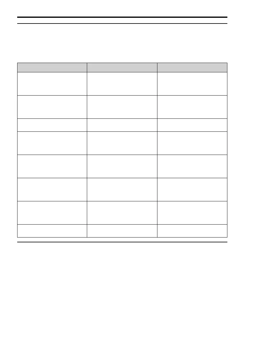
Table 15.5 Control Circuit Terminal Power Supplies
Input/Output Terminals Power Supply Specifications
Digital input S1 to S7, SN, SC, SP
Uses the LVLC power supply in the
drive.
Use the UL Listed class 2 power
supply for external power supply.
Analog input A1, A2, AC ,+V
Uses the LVLC power supply in the
drive.
Use the UL Listed class 2 power
supply for external power supply.
Analog output AM, AC
Uses the LVLC power supply in the
drive.
Pulse train output MP, AC
Uses the LVLC power supply in the
drive.
Use the UL Listed class 2 power
supply for external power supply.
Pulse Train Input RP, AC
Uses the LVLC power supply in the
drive.
Use the UL Listed class 2 power
supply for external power supply.
Safe disable input H1, H2, HC
Uses the LVLC power supply in the
drive.
Use the UL Listed class 2 power
supply for external power supply.
Serial communication input/output D+, D-, AC
Uses the LVLC power supply in the
drive.
Use the UL Listed class 2 power
supply for external power supply.
24 V external power supply PS, AC
Use the UL Listed class 2 power
supply.
◆ Drive Motor Overload and Overheat Protection
The drive motor overload and overheat protection function complies with the National Electric
Code (NEC) and the Canadian Electric Code, Part I (CEC).
Set the Motor Rated Current and L1-01 through L1-04 [Motor Overload Protection Select]
correctly to enable motor overload and overheat protection.
Refer to the control method and set the motor rated current with E2-01 [Motor Rated Current
(FLA)], E5-03 [PM Motor Rated Current (FLA)], or E9-06 [Motor Rated Current (FLA)].

 Loading...


