8 Electrical Installation
YASKAWA TOEPC71061752B GA500 Drive Installation & Primary Operation 39
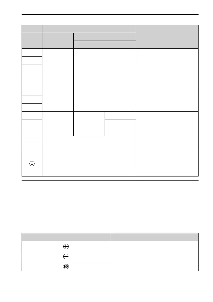
Table 8.2 Main Circuit Terminal Functions
Terminal Name
Function
Model B001 - B018
2001 - 2082
4001 - 4060
R/L1
- Main circuit power supply input
To connect a commercial power supply.
S/L2
T/L3
L/L1
Main circuit power
supply input
-
N/L2
U/T1
Drive output Drive output To connect a motor.V/T2
W/T3
-
DC power input DC power input
-
+1 and +2: To connect a DC link choke.
Note:
Remove the jumper between
terminals +1 and +2 to connect a DC
link choke.
+1
DC link choke
connection
+2 - -
B1
Braking resistor connection
To connect a braking resistor or braking
resistor unit.
B2
Ground Wiring
To ground the drive.
• 200 V: D class grounding (ground to
100 Ω or less)
• 400 V: C class grounding (ground to
10 Ω or less)
◆ Wire Selection
Select the correct wires for main circuit wiring.
Refer to Main Circuit Wire Gauges and Tightening Torques on page 136 for wire gauges and
tightening torques as specified by European standards.
Refer to Main Circuit Wire Gauges and Tightening Torques on page 162 for wire gauges and
tightening torques as specified by UL standards.
These tables use icons in Table 8.3 to show the shapes of the screw heads.
Table 8.3 Icons to Identify Screw Shapes
Icon Screw Shape
+/-
Slotted (-)
Hex socket cap (WAF: 5 mm)

 Loading...


