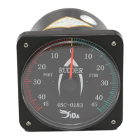
Rudder Angle Indicator Complete Set
(45C-0183/ RD-0183)
Manual
Ⅰ.General
High-precision angle sensor is applied to transmitter, generating digital signal output; RS422 NMEA
0183 format will be output by MCU, MCU employed in rudder meter will convert the digital signal and
drive the step electric motor inside, indicating corresponding ±0~45° rudder angle.
Ⅱ.Technical Parameters
Working Volt: DC22~32V(standard DC24V)
Working Temp: -10~60℃
Range: ±0~45°
Deviation: <1°
Anti-fog class: 35
Ⅲ.Installment and Commission
1. Install transmitter: connect the rod with transmitter, turn left and right of the transmitter, make sure
the meter indication comply with transmitter, if opposite, change the signal-output cable. Position
the transmitter by using mounting plate until the indication is correct.
2. 0 °check: place the rudder blade at 0 °, adjust the transmitter to 0 °(Note: the 0 °of rudder blade and
transmitter must be correctly checked, or the precision will be reduced); later, install meter and
connect the power(DC24V) cable(must be correct); next, connect the cables of transmitter to rudder
meter, blue for A﹢, green for B﹣, black for GND, red for 12v. Turn power on after finishing the
correct connection, the meter will display 0 ° (note: the 0 °has been checked,please don’t adjust it
again).
3. ±45° adjustment: place the rudder blade at full degree, check the meter and adjust the rod to make
sure the ±45° correct.
4. The 0 °of rudder blade and transmitter must be correctly checked, or the indication difference (left
and right) of the meter will be big.
5. CW/CCW and GND , if the pointer indicates opposite direction with
rudder angle, please connect CW/CCW with GND for one time, the indication will go with rudder
angle direction.
6. DIM: for the light adjustment, UP and DOWN; POWER: shows power on; WORK: indicates
communication is in process.