669997-UAI-H-0514
2 Johnson Controls Unitary Products
INSTALLATION
Installation is the same for all Rev B model air handler operating
positions: upflow, downflow, and horizontal right or left. Only the
Rev B model air handler will work on the downflow position.
Installation of the Heater Kit should be done prior to unit instal-
lation in accordance with Table 2. Refer to figure 1 for depiction
of components.
1. Remove air handler blower access panel.
2. If Heat Kit has circuit breakers (if heat kit does not contain
circuit breakers, skip to step 3):
a. Examine the heat kit and take note of the number of
circuit breakers it has. Remove the appropriate num-
ber of circuit breaker knockouts from front of air han-
dler unit.
b. Cut blower access panel insulation behind the circuit
breaker plate and remove to open the area for the cir-
cuit breakers to protrude through the front access
panel and to provide clearance for circuit breakers and
single point wiring entry kit.
c. Replacement non-foil faced insulation for the exposed
front panel may then need to be added. Add rubber
gasket to inside of door for sealing.
3. Remove and recycle the duct cover from back panel of air
handler control and wiring compartment.
4. Install electric heat accessory.
a. Position and insert heat kit into opening in air handler.
b. Align mount holes and fasten the Heat Kit to the air
handler unit with 4 duct cover screws.
5. Remove and discard the air handler power connection wir-
ing that is for use without electric heat (the connector con-
taining only the red and black wires) from the 6 pin
connector.
6. Connect the heat kit's 6 pin socket connector to the control/
power 6 pin connector in the air handler. The end terminals
are “D” shaped to ensure polarization of the connector.
7. Mark an X in the appropriate box on the indoor unit rating
plate for the particular heater installed.
8. Refer to the unit rating plate for the minimum blower speed
required for the model heat kit installed.
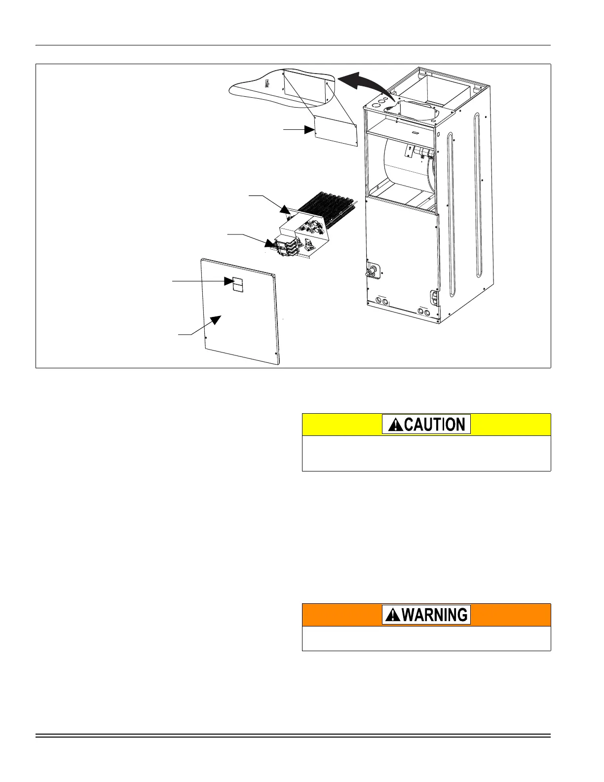
FIGURE 1: Heater Installation
FIELD SUPPLY WIRING
LEFT SIDE
5.
SLIDE HEATER KIT INTO
AIR HANDLER AND ATTACH
WITH 4 DUCT COVER SCREWS
4.
BLOWER
ACCESS PANEL
1.
IF HEAT KIT TO BE INSTALLED
HAS FACTORY INSTALLED
CIRCUIT BREAKERS,
REMOVE CIRCUIT BREAKER
KNOCKOUTS.
2.
REMOVE
DUCT COVER
3.
A027-001
To prevent damage, carefully pass the accessory heating ele-
ment through the rectangular opening in the discharge duct.
Element mounting plate must be secured with 4 screws.
Verify edges of foil faced insulation are not in contact with any
exposed electrical connections.
 Loading...