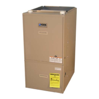
036-21120-001 Rev. A (201) YORK
2 Unitary Products Group
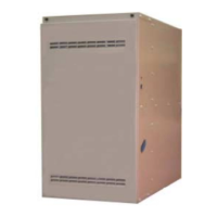
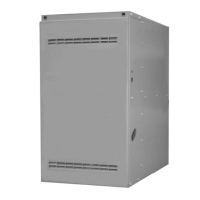
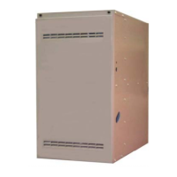
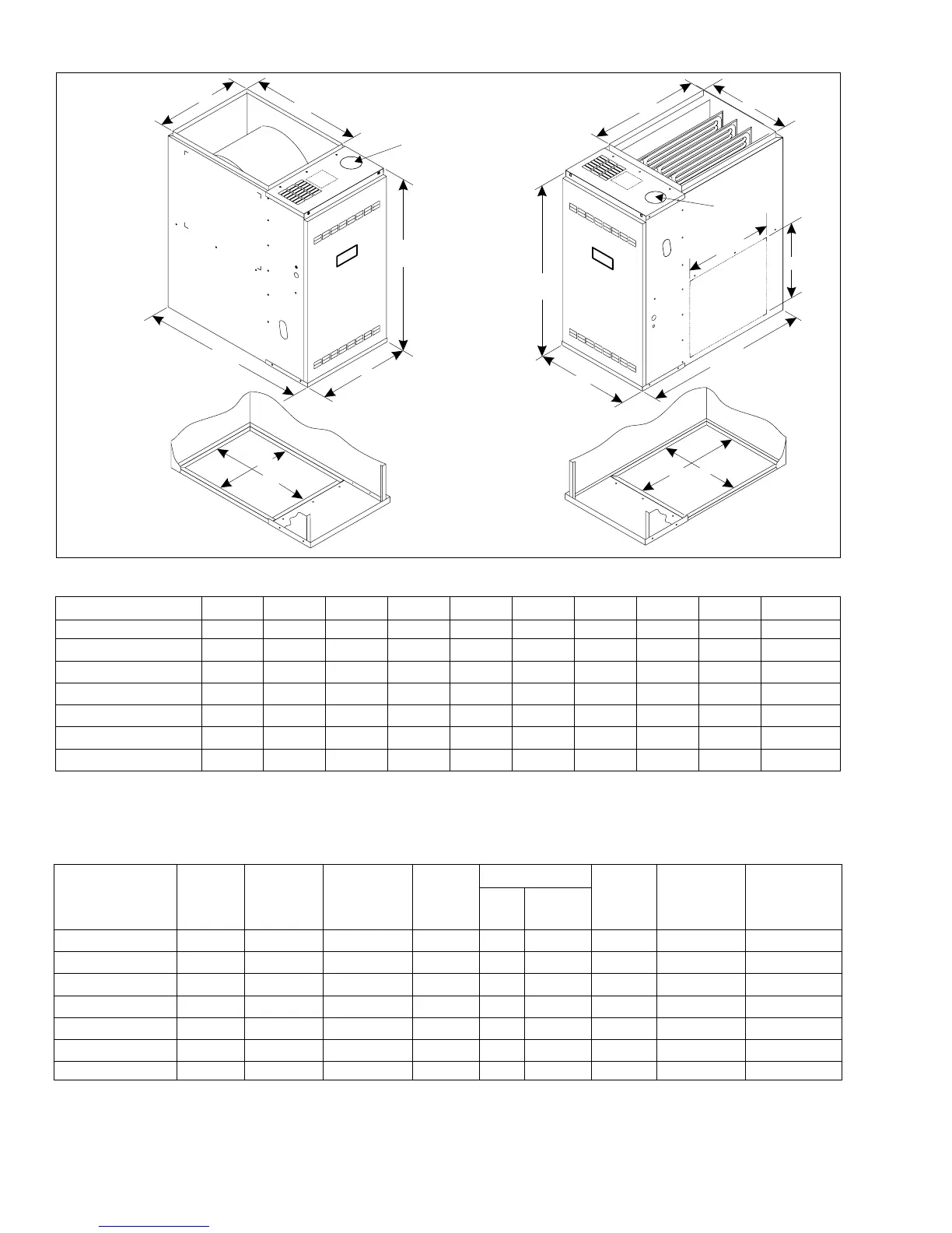
FURNACE DIMENSIONS
RATINGS & PHYSICAL/ELECTRICAL DATA
1 May be subtituted as G8C*****MD for factory shipped downflow models.
NOTE:For altitudes above 2,000 ft., reduce capacity 4% for each 1,000 ft. above sea level.
Wire size based on copper conductors, 60° C, 3% voltage drop.
Continuous return air temperature must not be below 55° F.
MODEL ABCDEFGHJK (VENT)
G8C05012MUB11
1
1 May be subtituted as G8C*****MD for factory shipped downflow models.
17-1/2 16-1/2 20-3/8 20 16 14-3/4 18-3/4 15-1/8 19 3
G8C07512MUB11
1
17-1/2 16-1/2 20-3/8 20 16 14-3/4 18-3/4 15-1/8 19
4
2
2 All models are supplied with 3" vent connections. An installer supplied transition to 4" or 5" must be used where necessary.
** Upflow / Horizontal only.
Dimensions "B", "C", "D" & "E" are with duct flanges turned up. "F", "G", "H" & "J" are with flanges flat.
G8C07516MUC11
1
21 20 20-3/8 20 19-1/2 18-1/4 18-3/4 18-5/8 19
4
2
G8C10016MUC11
1
21 20 20-3/8 20 19-1/2 18-1/4 18-3/4 18-5/8 19
4
2
G8C10020MUD11
1
24-1/2 23-1/2 20-3/8 20 23 21-3/4 18-3/4 22-1/8 19
4
2
G8C12520MUD11
1
24-1/2 23-1/2 20-3/8 20 23 21-3/4 18-3/4 22-1/8 19
5
2
G8C15020UHD11** 24-1/2 23-1/2 20-3/8 20 23 21-3/4 18-3/4 22-1/8 19
5
2
MODEL
HEAT
CAP.
INPUT
MBH
OUTPUT
MBH
AIR TEMP
RISE °F
MAX.
OUTLET
TEMP. °F
BLOWER
TOTAL
UNIT
AMPS
MAX.
OVER-
CURRENT
BREAKER
MIN. WIRE
SIZE (AWG)
@ 75 FT.
ONE WAY
HP SIZE
G8C05012MUB11
1
50 40 30-60 160 1/3 10 x 8 6.7 15 14
G8C07512MUB11
1
75 60 35-65 165 1/3 10 x 8 6.7 15 14
G8C07516MUC11
1
75 60 30-60 160 1/2 10 x 10 8.5 15 14
G8C10016MUC11
1
100 80 40-70 170 1/2 10 x 10 8.5 15 14
G8C10020MUD11
1
100 80 35-65 165 3/4 (2) 10 x 6 10.3 15 14
G8C12520MUD11
1
125 100 40-70 170 3/4 (2) 10 x 6 10.3 15 14
G8C15020UHD11** 150 120 40-70 170 3/4 (2) 10 x 6 10.3 15 14
DOWNFLOW
UPFLOW
A
A
B
E
D
BOTTOM VIEW
F
G
29-3/4
29-3/4
C
31-1/2
31-1/2
14
BOTTOM VIEW
H
J
16-1/4
K
K
 Loading...