Do you have a question about the York UL R134A and is the answer not in the manual?
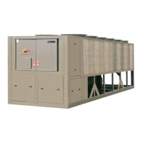
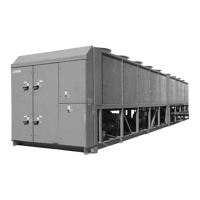
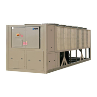
Introduction to the YORK YCIV model air cooled screw liquid chillers.
Details on the power and electrical requirements and features of the chiller system.
Description of the semi-hermetic twin screw compressors used in the chillers.
Explanation of the refrigerant circuit components and design for reliability.
Details on the high-efficiency, direct-expansion evaporator design and features.
Description of the condenser section, including fan and coil specifications.
Information on the advanced microprocessor control system and its features.
Information on the chiller being shipped as a complete, factory-assembled package.
Various options available to reduce chiller sound levels for different applications.
Details on the optional factory-mounted circuit breaker for power panel protection.
Options for protecting condenser coils against corrosion in various environments.
Protective panels available for the chiller, such as louvered or wire panels.
Options available for the evaporator, such as insulation and flange accessories.
Interface options for connecting the chiller to a Building Automation System.
Different types of vibration isolation options available for unit mounting.
Explanation of how the model number denotes unit characteristics like voltage and refrigerant.
Table showing the minimum and maximum leaving water temperatures for various models.
Table detailing the minimum and maximum cooler flow rates in GPM for different models.
Table showing the minimum and maximum air temperatures on the condenser in Fahrenheit.
Table showing minimum and maximum leaving water temperatures in Celsius.
Table of minimum and maximum cooler flow rates in liters per second.
Table of minimum and maximum air temperatures on the condenser in Celsius.
Graph illustrating pressure drop vs. water flow rate for two-circuit evaporators.
Graph showing pressure drop vs. water flow rate in SI units for two-circuit evaporators.
Graph showing pressure drop vs. water flow rate for three-circuit evaporators.
Graph illustrating pressure drop vs. water flow rate in SI units for three-circuit evaporators.
Tables with Tons, KW, and EER ratings for various LCWT and air temperatures.
Tables showing Tons, KW, and EER for High Efficiency models at different operating conditions.
Tables showing kW output, kW input, and COP for SI units at 460V/60Hz.
Tables showing high efficiency ratings for SI units at 460V/60Hz.
Tables detailing standard efficiency ratings for SI units at 400V/50Hz.
Tables showing high efficiency ratings for SI units at 400V/50Hz.
Tables showing Tons, KW, and EER for standard efficiency English units at 380V/60Hz.
Tables detailing high efficiency ratings for English units at 380V/60Hz.
Tables showing kW output, kW input, and COP for SI units at 380V/60Hz.
Tables showing high efficiency ratings for SI units at 380V/60Hz.
General data including refrigerant charge, oil charge, and number of compressors.
Specifications for condenser coils and fans.
Physical data for the direct expansion evaporator.
General unit data for high efficiency models, including refrigerant and oil charge.
Condenser coil and fan specifications for high efficiency units.
Physical data for the direct expansion evaporator in high efficiency models.
General unit data in SI units, including refrigerant and oil charge.
Condenser coil and fan specifications in SI units.
Physical data for the direct expansion evaporator in SI units.
General unit data in SI units for high efficiency models.
Condenser coil and fan specifications in SI units for high efficiency models.
Evaporator physical data in SI units for high efficiency models.
Dimensional drawings for YCIV0157E/V and YCIV0157S/P models.
Dimensional drawings for YCIV0177 and YCIV0187 series models.
Dimensional drawings for YCIV0197, YCIV0207, and YCIV0227 models.
Dimensional drawings for YCIV0207E/V and YCIV0227E/V models.
Dimensional drawings for YCIV0247 and YCIV0267 models.
Dimensional drawings for YCIV0267E/V and YCIV0287S/P models.
Dimensional drawings for the YCIV0287E/V model.
Dimensional drawings for the YCIV0307S/P model.
Dimensional drawings for YCIV0327E/V and YCIV0357S/P models.
Dimensional drawings for YCIV0357E/V and YCIV0397S/P models.
Dimensional drawings in SI units for YCIV0590E/V and YCIV0600S/P models.
Dimensional drawings in SI units for YCIV0630, YCIV0650, YCIV0700, and YCIV0720 models.
Dimensional drawings in SI units for YCIV0760, YCIV0770, and YCIV0890 models.
Dimensional drawings in SI units for YCIV0800E/V and YCIV0830E/V models.
Dimensional drawings in SI units for YCIV0920, YCIV0930, and YCIV1000 models.
Dimensional drawings in SI units for YCIV1050E/V and YCIV1070S/P models.
Dimensional drawings in SI units for the YCIV1120E/V model.
Dimensional drawings in SI units for the YCIV1180S/P model.
Dimensional drawings in SI units for YCIV1220E/V and YCIV1340S/P models.
Dimensional drawings in SI units for YCIV1380E/V and YCIV1500S/P models.
Table showing isolator locations and point loads for standard efficiency English models.
Table showing isolator locations and point loads for high efficiency English models.
Table showing isolator locations and point loads for standard efficiency SI models.
Table showing isolator locations and point loads for high efficiency SI models.
Details and cross-reference for one-inch deflection spring isolators.
Details and cross-reference for neoprene isolator cross-reference.
Details on SLRS two-inch deflection seismic spring isolators.
Electrical data for 2-compressor standard efficiency units, System 1 configurations.
Electrical data for 2-compressor standard efficiency units, System 2 configurations.
Electrical data for 2-compressor high efficiency units, System 1 configurations.
Electrical data for 2-compressor high efficiency units, System 2 configurations.
Electrical data for 3-compressor standard efficiency units, System 1 configurations.
Electrical data for 3-compressor standard efficiency units, System 2 configurations.
Electrical data for 3-compressor high efficiency units, System 1 configurations.
Electrical data for 3-compressor high efficiency units, System 2 configurations.
Abbreviations and definitions used in the electrical diagrams and notes.
Important notes regarding U.L. labeling, wiring configurations, and conductor types.
Wiring diagrams for 2-compressor power connections, showing circuit breaker and terminal block options.
Wiring diagrams for 3-compressor power connections, single point configurations.
Detailed control wiring diagram for a two-compressor chiller unit.
Detailed control wiring diagram for a three-compressor chiller unit.
Guidelines for selecting an appropriate outdoor installation site for the chillers.
Requirements for unit mounting foundations, including ground and roof installations.
Recommendations for chilled liquid piping system layout, including valves and strainers.
General requirements for the chiller installation, including scope, quality assurance, and warranty.
Product specifications, including manufacturers and general descriptions.
General requirements for products, including manufacturers and design specifications.
Detailed specifications for compressors, motors, and lubrication systems.
Components included in each independent refrigerant circuit.
Specifications for the evaporator and air-cooled condenser.
Further details on heat exchanger specifications, including coils and subcooling.
Detailed requirements for the chiller's power supply, panel, and wiring.
Information on the chiller's control system, display, and programmable setpoints.
Power factor requirements and wiring protection details.
Available accessories and options that can be added to the chiller unit.
Further details on accessories like evaporator options and sound reduction.
Procedures and requirements for the installation of the chiller unit.
