YORK INTERNATIONAL
116
FORM 150.62-NM7 (103)
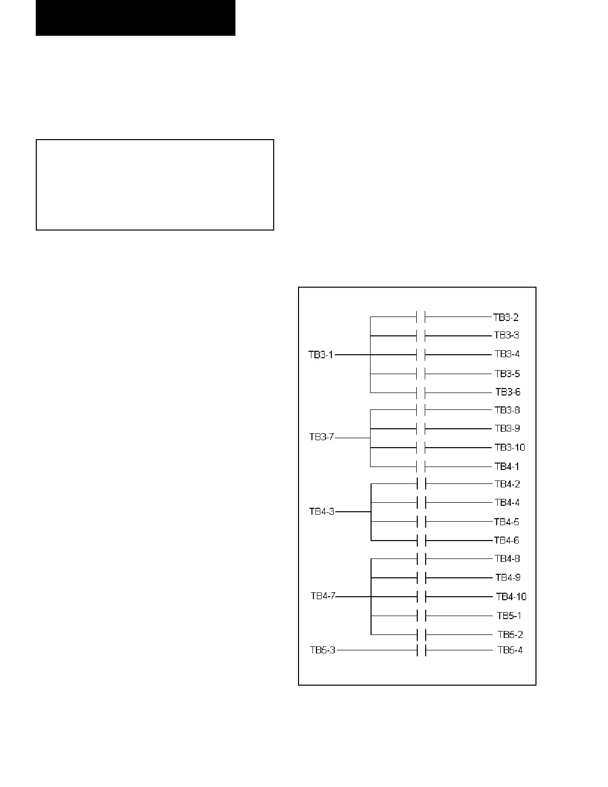
FIG. 14 – MICROBOARD RELAY CONTACT
ARCHITECTURE
LD03842
The suction transducers have a range from 0 to 200
PSIG (13.79 BARG). The output will be linear from
.5VDC to 4.5VDC over the 200 PSIG (13.79 BARG)
range. Fol low ing is a formula that can be used to verify
the voltage output of the transducer. All voltage reading
are in ref er ence to ground (unit case).
V = (Pressure in PSIG x .02) + .5
or
V = (Pressure in BARG x .29) + .5
where V = dc voltage input to micro
Pressure = pressure sensed by transducer
Following are the microboard connections for the Suc-
tion Transducer:
System 1 Suction Transducer
J4-5 = +5VDC regulated supply to transducer.
J4-10 = VDC input signal to the microboard.
See the formula above for voltage read ings
that correspond to specifi c suction pres sures.
J4-1 = +5VDC return
J4-2 = drain (shield connection = 0VDC)
System 2 Suction Transducer
J7-5 = +5VDC regulated supply to transducer.
J7-10 = VDC input signal to the microboard.
See the formula above for voltage read ings
that correspond to specifi c suction pres sures.
J7-1 = +5VDC return
J7-2 = drain (shield connection = 0VDC)
If the optional Suction Transducer is not used on the
YCAL0043 - YCAL0173, a Low Pressure switch will be
used. Following are the microboard con nec tions for the
Low Pressure switch.
System 1 Low Pressure Switch
J4-5 = +5VDC regulated supply to LP switch.
J4-10 = input signal to the microboard. 0VDC =
open switch / +5VDC = closed switch.
J4-2 = drain (shield connection = 0VDC)
System 2 Low Pressure Switch
J7-5 = +5VDC regulated supply to LP switch.
J7-10 = input signal to the microboard. 0VDC = open
switch / +5VDC = closed switch.
J7-2 = drain (shield connection = 0VDC)
Service and Trou ble shoot ing
DIGITAL OUTPUTS
Refer to the unit wiring diagram and Fig. 14 and Table
34. The dig i tal out puts are located on TB3, TB4, and TB5
of the mi cro board. ALL OUTPUTS ARE 120VAC with
the ex cep tion of TB5-3 to TB5-4. TB5-3 to TB5-4 are the
con tacts that can be used for an evaporator pump start
sig nal. The voltage applied to either of these terminals
would be de ter mined by fi eld wiring.
Each output is controlled by the microprocessor by
switch ing 120VAC to the respective output con nec tion
energizing contactors, evaporator heater, and so le noids
ac cord ing to the operating se quence.
120VAC is supplied to the microboard via con nec tions
at TB3-1, TB3-7, TB4-3, and TB4-7. Figure 14 il lus trates
the relay contact ar chi tec ture on the microboard.
 Loading...


