2 Johnson Controls Unitary Products
246750-YTG-M-0908
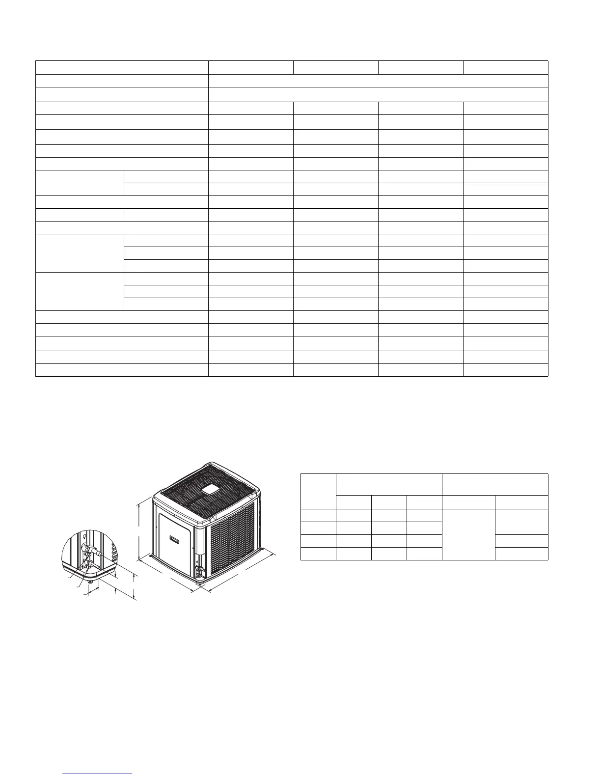
All dimensions are in inches. They are subject to change with-
out notice. Certified dimensions will be provided upon request.
* Adapter fitting required for 1-1/8” line set.
Physical and Electrical Data
MODEL
YZE02411 YZE03611 YZE04811 YZE06011
Unit Supply Voltage 208-230V, 1φ, 60Hz
Normal Voltage Range
1
187 to 252
Minimum Circuit Ampacity 18.6 24.7 27.9 37.9
Max. Overcurrent Device Amps
2
30 40 45 60
Min. Overcurrent Device Amps
3
20 25 30 40
Multi-stage Compressor Yes Yes Yes Yes
Compressor Type Scroll Scroll Scroll Scroll
Compressor Amps
Rated Load 13.7 18.6 21.2 29.2
Locked Rotor 52 82 96 118
Crankcase Heater No No No No
Fan Motor Amps Rated Load 1.5 1.5 1.5 1.5
Fan Diameter Inches 22 22 22 22
Fan Motor
Rated HP 1/4 1/4 1/4 1/4
Nominal RPM 850 850 850 850
Nominal CFM 3,250 3,300 3,050 3,100
Coil
Face Area Sq. Ft. 17.15 20.58 20.58 20.58
Rows Deep 1122
Fins / Inch 22 22 22 22
Liquid Line Set OD (Field Installed) 3/8 3/8 3/8 3/8
Vapor Line Set OD (Field Installed) 3/4 3/4 7/8 7/8
Unit Charge (Lbs. - Oz.)
4
8 - 14 8 - 8 14 - 8 14 - 0
Charge Per Foot, Oz. 0.62 0.62 0.67 0.75
Operating Weight Lbs. 270 290 310 315
1. Rated in accordance with ARI Standard 110, utilization range “A”.
2. Dual element fuses or HACR circuit breaker. Maximum allowable overcurrent protection.
3. Dual element fuses or HACR circuit breaker. Minimum recommended overcurrent protection .
4. The Unit Charge is correct for the outdoor unit, matched indoor coil and 15 feet of refrigerant tubing. For tubing lengths other than 15 feet,
add or subtract the amount of refrigerant, using the difference in length multiplied by the per foot value.
VAPOR
LIQUID
2-3/8
3-1/8
6-1/2
C
A
B
Unit
Model
Dimensions
(Inches)
Refrigerant Connection
Service Valve Size
A B C Liquid Vapor
024 33-1/2 37 31
3/8”
3/4”
036 39-1/2 37 31
048 39-1/2 37 31 7/8”
060 39-1/2 37 31 7/8”*

 Loading...