VER. 002_17.06.2016
MOUNTING
1. Disconnect the power supply from the mains
by: the phase fuse, circuit-breaker or switch
disconnector joined to the proper circuit,
2. By means of special equipment check if
there is no voltage on connection cables.
3. After unscrewing the screw, carefully remove
the upper cover.
4. Choose mounting place on the wall, make two
holes corresponding to mounting holes of the
temperature controller’s base.
5. Set wall plugs in the holes.
6. Pull Installation cables through holes in the
base.
7. Mount the base by means of screws, screw
them into the wall plugs.
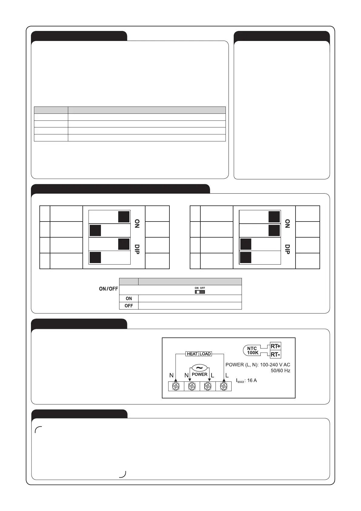
8. Connect the cables with the terminals accor
-
ding to the installing diagram.
9. Connect the external sensor to the RT2-, RT2+
terminals, if necessary.
10. Adjust controller’s operation parameters by
means of operation mode switch.
11. Place the upper cover on the base.
12. Screw the regulator’s base. Only ø3 mm
screws can be used and with maximum length
of 8 mm.
13. Switch on the power supply from the mains and
check the regulator’s operation.
CAUTION:
the cable with oor sensor must not
be shortened.
OPERATING
During standard operation the LCD display shows current room temperature. Current temperature ad-
justment is shown in pulsating form while turning the knob.
Temperature adjustment
Adjust required temperature by means of controller’s knob. Adjusted temperature will be shown in
pulsating form on the LCD display. After some time it will stop and show current room temperature.
Heating status: The ame symbol appears when the controller starts heating.
The controller is equipped with built-in (internal) temperature sensor and terminals marked as RT2-,
RT2+ used for external (oor) temperature sensor connection. If the external sensor is connected to
the terminals then the temperature is controlled by the external sensor. Otherwise the temperature
controller will use the built-in controller.
Error chart (Error symbol pulsates on the LCD display)
Symbol Description
„E1” pulsates Short-circuit of internal sensor. The temperature controller cuts off the output.
„E2” pulsates Room sensor damage. The temperature controller cuts off the output.
„E3” pulsates Short-circuit of external (oor) sensor. The temperature controller cuts off the output.
„E4” pulsates Floor sensor damage. The temperature controller cuts off the output.
In case of internal(oor) sensor breakdown, the temperature is controlled by (built-in) internal sensor.
If the room temperature is higher than 30ᵒC, than „HI“symbol appears on the display. Then in the
heating mode the controller’s output is cut off, whereas in the cooling mode cooling should start. If
the room temperature is lower than 5ᵒC than „LO“symbol appears on the display. In the heating mode
heating should start and in the cooling mode cooling should switch off.
GUARANTEE CARD
There is 24 months guarantee on the product
Salesman stamp and signature, date of sale
1. ZAMEL Sp. z o.o. assures 24 months guarantee for the product.
2. The manufacturer’s guarantee does not cover any of the following actions:
a) mechanical damage during transport, loading / unloading or under other circumstances,
b) damage caused by incorrect product mounting or misuse,
c) damage caused by unauthorised modications made by the PURCHASER or any third parties to the product or any other devices
needed for the product functioning,
d) damage caused by Act of God or any other incidents independent of the manufacturer - ZAMEL Sp z o.o.
e) power supply (batteries) to be equipped with a device in the moment of sale (if they appear);
3. The PURCHASER shall lay any claims in writing to the dealer or ZAMEL Sp. z o.o.
4. ZAMEL Sp. z o.o. is liable for processing any claim according to current Polish legislation.
5. ZAMEL Sp. z o.o. shall process the claim at its own discretion: product repair, replacement or money return.
6. The manufacturer’s guarantee is valid in the Republic of Poland.
7. The PURCHASER’s statutory rights in any applicable legislation whether against the retailer arising from the purchase contract or
otherwise are not affected by this warranty.
CONNECTING
Electric oor heating system
SWITCHES ADJUSTEMENT CONFIGURATION
Mode Description
mode switch set on:
the relay is switched on
the relay is switched off
1
°F °C
2
ROOM
3
FLOOR
4
10-16 A 3-8 A
1
°F °C
2
ROOM
3
FLOOR
4
10-16 A 3-8 A
ºF / ºC degree – temperature unit, ROOM, FLOOR
Temperature control from internal sensor
Temperature control from external sensor (at the oor)
 Loading...