5
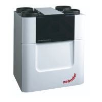
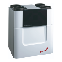
Installation instructions unity ZCV2
This ventilator has been developed for continuous operation to ensure the necessary basic ventilation in buildings. Boost
ventilation can be activated manually (this requires a second, switched „L1“ phase) or via a humidity sensor (a permanent „L“
phase is sufficient here) as needed. Please read these installation instructions completely before starting work.
Caution:
Ensure that all electric power is turned off before carrying out any work. The electrical connections may only be conducted by a
suitably qualified electrician and must comply with the locally applicable regulations.
Where an open-flued oil or gas-fuelled appliance is installed in the kitchen, extract ventilation can cause the spillage of flue
gases. Care must be taken to ensure ventilation is reduced appropriately, as set out in the Building Regulations. Kitchens with
solid-fuel appliances should not have extract fans fitted.
Warning: The appliance is not intended for use by young children or infirm persons unless they have been adequately supervised
by a responsible person to ensure that they can use the appliance safely. Young children should be supervised to ensure that
they do not play with the appliance.
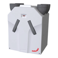
Wall/ceiling installation
Remove the cover by turning counterclockwise, loosen the 3 holding screws and carefully open the cover with the control panel.
Install an air duct with internal diameter of 100 mm in the wall or ceiling. For wall installation make sure the duct runs to the
outside with a slight gradient. For ceiling installation you must insulate the air duct if it passes through unheated areas.
The power cable should be sited with a spacing of X = 65 mm from the centre of the air duct. You will need a switched „L1“
phase in addition to the continuous „L“ phase for manual activation of the „boost ventilation“ function.
Feed the power cable through the provided opening (A) and screw the unit to the wall or ceiling with four screws. Ensure 2
positioning arrows are pointing upwards when installing in wall application.
Strip the cable as shown in (B) and connect according to the circuit diagram. The ventilator is double insulated and does not
require a protective earth conductor. If the house has an earth conductor, this can be „parked“ at the terminal (C). Secure the
connected cable with the cord grip (D).
Then reclose the cover with the control panel and screw it down.
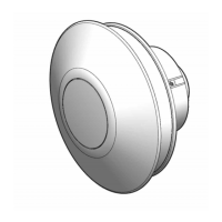
Attach a safety guard to the air duct outlet on the outside.
Start-up/settings
Set the house switch for manual boost ventilation to OFF (no power to „L1“) and switch the main circuit breaker back on.
Use the control panel to start-up and adjust the ventilator.
As soon as the ventilator is reconnected to the power supply, the two buttons flash and for max. 15 minutes.
If you now press, for example, the button , the factory setting „Boost ventilation/small bathroom“ is activated and
flashes .
9-10
1-2
3
4
5-6
7-8
11
12
13
14
Factory settings
Room Basic ventilation Boost ventilation
Small bathroom 18 m
3
/h 30 m
3
/h
Kitchen / large bathroom
30 m
3
/h
50 m
3
/h
The factory setting can be altered using button and and, thus, adjusted to the applicable room situation. To confirm the
setting press button , the indicator lamp is now permanently illuminated. Repeat for „Basic ventilation/small bathroom”
mode adjustment. To confirm the setting press button . The settings mode ends automatically after 10 seconds without
entry.
The new type of humidity sensor registers the speed at which the humidity in the room changes. If there is a rapid change it
reacts to a rise in room humidity caused by the user and switches on the ventilator. Press button to activate the humidity
sensor. The LED lamp illuminates to indicate that the sensor is active.
Activate the post-run timer (only with connected switched „L1“ phase) by pressing button . The length of post-running time
depends on how long the ventilator was manually switched to the „Boost ventilation“ mode.
An active sensor is indicated by the illumination of the LED lamp.
Pressing any button displays the current operating status. To change the setting you need to press button and
simultaneously for approx. 3 seconds. Press button and for approx. 10 sec. to reactivate the factory setting.
Reattach the cover by turning clockwise.
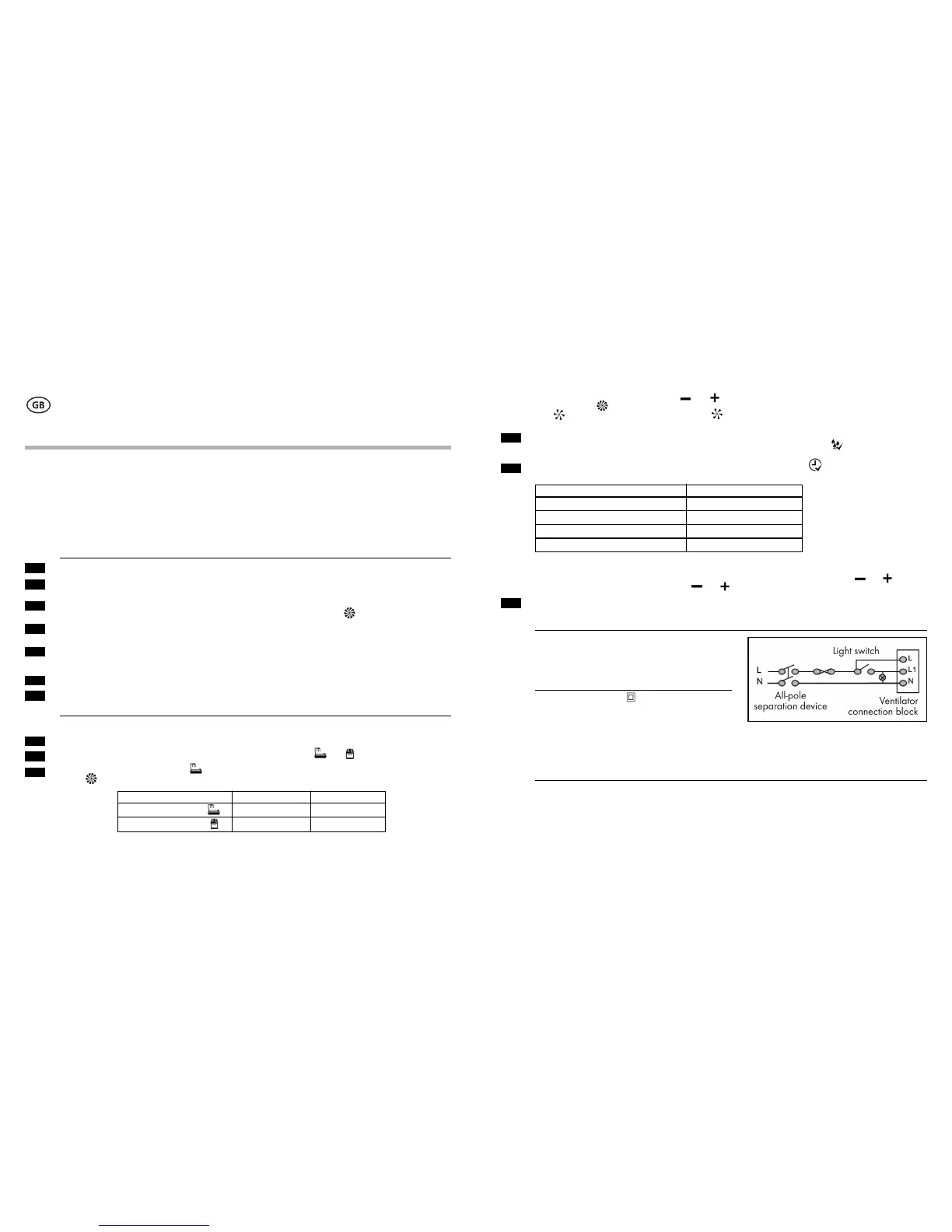
Wiring Diagram:
The voltage and frequency of the power supply must match the
ventilator’s specifications. An all-pole separation device from the
mains with a contact gap of at least 3 mm is stipulated where
the ventilator is installed. Installation in humid rooms must be
effected in accordance with local regulations.
Technical data:
Protection class/type: IP 24
Mains voltage: 230 V~50 Hz
Power input: 1.1–4.1 W
Sound pressure: e.g. 23.5 dB(A) 3 m with 30 m
3
/h
e.g. 33 dB(A) 1 m with 30 m
3
/h
Capacity: 10–76 m
3
/h
Max. supply pressure 110 Pa
Max. supply temperature: 40 °C
Max. duct: 6 m
Cleaning and maintenance:
Clean the cover and the housing with control panel with a damp cloth. Do not use aggressive cleaning agents!
We reserve the right to make technical changes.
15
16
17
Manual turn-on time (L1 active) Post-run timer
0–5 min. No post-running
5–10 min. 5 minutes
10–15 min. 10 minutes
15 + min. 15 minutes
4
 Loading...