1
© Copyright 2008 Zoeller Co. All rights reserved.
INSTALLATION IN STRUC TIONS
RECOMMENDED MODELS
P/N 006355
Notice to installing contractor: Instructions must remain with installation.
SECTION: 6.10.001
FM0447
0108
Supersedes
0207
PREINSTALLATION CHECKLIST - ALL IN STAL LA TIONS
*Effl uent systems should specify that pumps should not handle solids exceeding three fourths inch (¾") in order to prevent large solids from entering leeching fi elds, mound systems and
etc. (Model 49 and 70 Series have 3/8", 50, 90 and 140 Series have ½", 130 Series have 5/8", 150 Series have ¾" solids capability, 160/4160/180/4180 Series have ¾" solids capability.)
Where codes permit, sewage pumps can be used for effl uent systems. Nonautomatic pump(s) with external level control recommended for septic tank effl uent applications.
Product information presented
here re fl ects con di tions at time
of publication. Consult factory
re gard ing dis crep an cies or
in con sis ten cies.
MAIL TO: P.O. BOX 16347 • Louisville, KY 40256-0347
SHIP TO: 3649 Cane Run Road • Louisville, KY 40211-1961
(502) 778-2731 • 1 (800) 928-PUMP • FAX (502) 774-3624
visit our web site:
www.zoeller.com
DATE INSTALLED:
MODEL NUMBER:
1. Inspect your pump. Occasionally, products are damaged during shipment. If the unit is damaged, contact your dealer before using. DO NOT remove the test plugs in the cover nor the motor housing.
2. Carefully read the literature provided to familiarize yourself with specifi c details regarding in stal la tion and use. These materials should be retained for future reference.
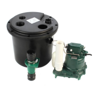
NOTICE: VENT HOLE FOR
CHECK VALVE
SEE #3 IN CAUTION SECTION
BELOW AND #6 ON PAGE 3
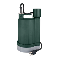
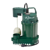
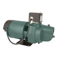
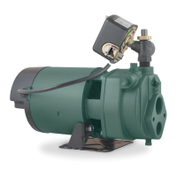
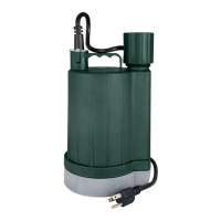
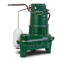
SEWAGE EFFLUENT* SUMP/DEWATERING
211 Series 53, 55, 57, 59 Series 49
264 Series 98 Series 72, 76 Series
266, 267, 268, 270, 4270 Series 137, 139, 140
, 4140,
Series
All Models
282, 284, 4282, 4284 Series
151, 152, 153 Series
292, 293, 294, 295, 4292, 4293, 4294, 4295 Series 161, 163, 165, 4161, 4163, 4165 Series
185, 186, 188, 189, 191, 4185, 4186, 4189 Series
SEE BELOW FOR
LIST OF CAUTIONS
SEE BELOW FOR
LIST OF WARNINGS
1. Make sure there is a properly grounded re cep ta cle avail able. All pumps are furnished with
provisions for proper grounding to protect you against the possibility of electrical shock.
(SEE WARN ING BELOW)
2. Make certain that the receptacle is within the reach of the pump’s pow er supply cord. DO NOT
USE AN EXTENSION CORD. Extension cords that are too long or too light do not deliver suffi cient
voltage to the pump motor. But, more important, they could present a safety haz ard if the insulation
were to become damaged or the con nec tion end were to fall into the sump.
3. Make sure the pump electrical supply circuit is equipped with fuses or circuit breakers of
proper capacity. A separate branch circuit is rec om mended, sized ac cord ing to the “National
Elec tri cal Code” for the current shown on the pump nameplate.
4. Testing for ground. As a safety measure, each electrical outlet should be checked for ground
using an Underwriters Laboratory Listed circuit analyzer which will indicate if the power, neutral
and ground wires are correctly connected to your outlet. If they are not, call a qualifi ed licensed
electrician.
5. For Added Safety. Pumping and other equipment with a 3-prong grounded plug must be connected
to a 3-prong grounded receptacle. For added safety the receptacle may be protected with a ground-
fault circuit interrupter. When a pump needs to be connected in a watertight junction box, the plug
can be removed and spliced to the supply cable with proper grounding. For added safety this circuit
may be protected by a ground-fault circuit in ter rupt er. The complete in stal la tion must comply with
the National Electrical Code and all applicable local codes and ordinances.
6. FOR YOUR PROTECTION, ALWAYS DISCONNECT PUMP FROM ITS POW ER SOURCE BE FORE
HANDLING. Single phase pumps are sup plied with a 3-prong ground ed plug to help protect you
against the possibility of electrical shock. DO NOT UNDER ANY CIRCUM STANCES RE MOVE THE
GROUND PIN. The 3-prong plug must be inserted into a mating 3-prong grounded receptacle.
If the in stal la tion does not have such a receptacle, it must be changed to the prop er type, wired
and ground ed in ac cor dance with the National Elec tri cal Code and all applicable local codes and
or di nanc es. Three phase pumps require motor starting devices with motor overload pro tec tion. See
FM0514 for simplex in stal la tions or FM0486 for duplex in stal la tions. Pumps must be in stalled in
ac cor dance with the National Electrical Code and all ap pli cable local codes and ordinances. Pumps
are not to be installed in locations clas si fi ed as hazardous in accordance with National Electrical
Code, ANSI/NFPA 70.
7. “Risk of electrical shock” Do not remove power supply cord and strain relief or connect conduit
directly to the pump.
8. Installation and servicing of electrical circuits and hardware should be performed by a qualifi ed
li censed electrician.
9. Pump installation and servicing should be performed by a qualifi ed person.
10. Risk of electric shock - These pumps have not been investigated for use in swimming pool and
marine areas.
11. According to the state of California (Prop 65), this product contains chemicals known to the state
of California to cause cancer and birth defects or other reproductive harm.
1. Check to be sure your power source is capable of handling the voltage re quire ments of the motor,
as indicated on the pump name plate.
2. The installation of automatic pumps with variable level fl oat switch es or nonautomatic pumps using
auxiliary variable level fl oat switches is the re spon si bil i ty of the in stall ing party and care should be
tak en that the tethered fl oat switch will not hang up on the pump apparatus or pit peculiarities and
is secured so that the pump will shut off. It is recommended to use rigid piping and fi ttings and the
pit be 18" or larger in diameter.
3. Information - vent hole purpose. It is necessary that all sub mers ible sump, effl uent, and sewage
pumps capable of handling various sizes of solid waste be of the bottom intake design to reduce
clog ging and seal failures. If a check valve is incorporated in the installation, a vent hole (approx.
3/16") must be drilled in the discharge pipe below the check valve and pit cover to purge the unit
of trapped air. Trapped air is caused by agitation and/or a dry basin. Vent hole should be checked
periodically for clogging. The 50 or 90 Series pumps have a vent lo cated in the pump housing
opposite the fl oat, ad ja cent to a housing lug, but an additional vent hole is recommended. The
vent hole on a High Head application may cause too much turbulence. You may not want to drill
one. If you choose not to drill a vent hole, be sure the pump case and impeller is covered with liquid
before connecting the pipe to the check valve and no inlet carries air to the pump intake. NOTE:
THE HOLE MUST ALSO BE BELOW THE BASIN COVER AND CLEANED PERIODICALLY. Water
stream will be visible from this hole during pump run periods.
4. Pump should be checked frequently for debris and/or build up which may interfere with the fl oat “on”
or “off” position. Repair and service should be performed by Zoeller Pump Company Authorized
Service Station only.
5. Dewatering and effl uent sump pumps are not designed for use in pits handling raw sewage.
6. Maximum operating temperature for standard model pumps must not ex ceed 130°F (54°C). Model
49 max. temperature must not exceed 104ºF (40ºC). The 70 and 211 Series max. temperature must
not exceed 110ºF (43ºC).
7. Pump models 188/4188, 189/4189, and 295/4295 nonautomatic pump must run totally submerged
and CSA certifi ed pumps must be operated submerged with “off - on” level controls.
8. Pump models 266, 267, 268, 137 and 139 must be operated in an upright position. Do not attempt
to start pump when tilted or laying on its side.
9. Do not operate a pump in an ap pli ca tion where the Total Dynamic Head is less than the minimum
Total Dynamic Head listed on the Pump Performance Curves.
10. Model 49 is for indoor use only.
REFER TO WARRANTY ON PAGE 2.
NOTE: Pumps with the “UL” mark and pumps with the “US” mark are tested to UL Standard UL778.
CSA Certifi ed pumps are certifi ed to CSA Standard C22.2 No. 108.