Tools Required:
• Hose Bibb Pressure gauge (Zurn Wilkins Model HGI-25)
• 9/16” wrench for bolt adjustment
• Pliers for cartridge removal
• Crescent wrench for bell removal
• Silicone based food grade o-ring grease
Testing:
1. If available, determine the incoming supply pressure for reference.
2. Install the pressure gauge
3. Openadownstreamxtureinsidethedwellingtostartowthroughthevalve.
4. Recordthereadingonthepressuregaugeforreference.Thisisthereducedowingpressure.
5. Closetheinsidefaucetorxtureandimmediatelyrecordthereadingonthepressuregauge.Thisisthereducedstatic
pressure and outlet set point of the valve.
6. Observe the gauge for 10 minutes.
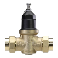
Model NR3XL
LEAD-FREE Pressure Reducing Valve with Integral By-pass
(1/2", 3/4", 1", 1-1/4" 1-1/2" & 2")
Installation Inspection Maintenance Repair Instructions
WARRANTY: ZURN WILKINS Valves are guaranteed against defects of material or workmanship when used for the services recom-
mended. If in any recommended service, a defect develops due to material or workmanship, and the device is returned, freight prepaid,
to ZURN WILKINS within 12 months from date of purchase, it will be repaired or replaced free of charge. ZURN WILKINS’ liability shall
be limited to our agreement to repair or replace the valve only.
ZURN WILKINS
1747 Commerce Way, Paso Robles, CA 93446 Phone:855-663-9876 Fax:805-238-5766
www.zurn.com
Annualinspectionandmaintenanceisrequiredofallplumbingsystemcomponents.Toensureproperperformanceandmaximum
life, this product must be subject to regular visual inspection and pressure testing, with cleaning or repair as needed. If the end user
isnotqualiedtoperformperiodicinspectionandmaintenance,aqualiedlicensedplumbermustbecontactedforassistance.It
is also recommended that a suitable strainer be installed upstream of the valve. Anytime a pressure reducing valve is adjusted, a
pressure gauge must be used downstream to verify correct pressure setting. Do not bottom out adjustment bolt on bell housing.
Where the desired pressure reduction is more than a 3 to 1 ratio (i.e. 225psi to 75psi), or inlet pressure is above 150 PSI multiple
regulators in series are recommended to be installed to prolong valve life.
Installation Instructions
1. Thisvalveshouldbeinstalledbyaqualiedlicensedplumber.
2. Flush supply line to remove loose dirt and scale which may damage the seal ring and seat.
3. Installvalvein-linewitharrowonvalvebodypointinginthedirectionofow.Thevalveshallbeinstalledinanaccessibleloca-
tion and may be installed in any orientation.
4. Allvalvesarefactorysettoapproximately50PSI,adjustregulatortodesiredoutletsetpressurebyturningadjustmentbolt
clockwise (into bell housing) to raise pressure or counterclockwise (out of bell housing) to reduce pressure.
NOTE: When reducing pressure open a downstream faucet to relieve pressure and use a pressure gauge
(Zurn Wilkins Model HGI-25) to verify correct pressure setting.
5. Tightenlocknutwhendesiredpressureisachievedandtestvalvetoconrmproperoperation.
Inspection and Maintenance Instructions
1
! WARNING: Cancer and Reproductive Harm - www.P65Warnings.ca.gov
! ADVERTENCIA: Cáncer y daño reproductivo - www.P65Warnings.ca.gov
! AVERTISSEMENT: Cancer et néfastes sur la reproduction - www.P65Warnings.ca.gov
WATER
METER
SHUT-OFF
VALVE
MODEL NR3XL
REGULATOR
MODEL 195XL
HOSE BIBB
HOSE BIBB
PRESSURE GAUGE
TO FIXTURES
INCOMING SUPPLY
PRESSURE
OUTLET SET POINT OF VALVE
(REDUCED STATIC PRESSURE)
0
180
14
0
100
60
2
0
80
120
160
200
psi
40