12 Guide on Installation and Debugging of Filters
Electrical connection
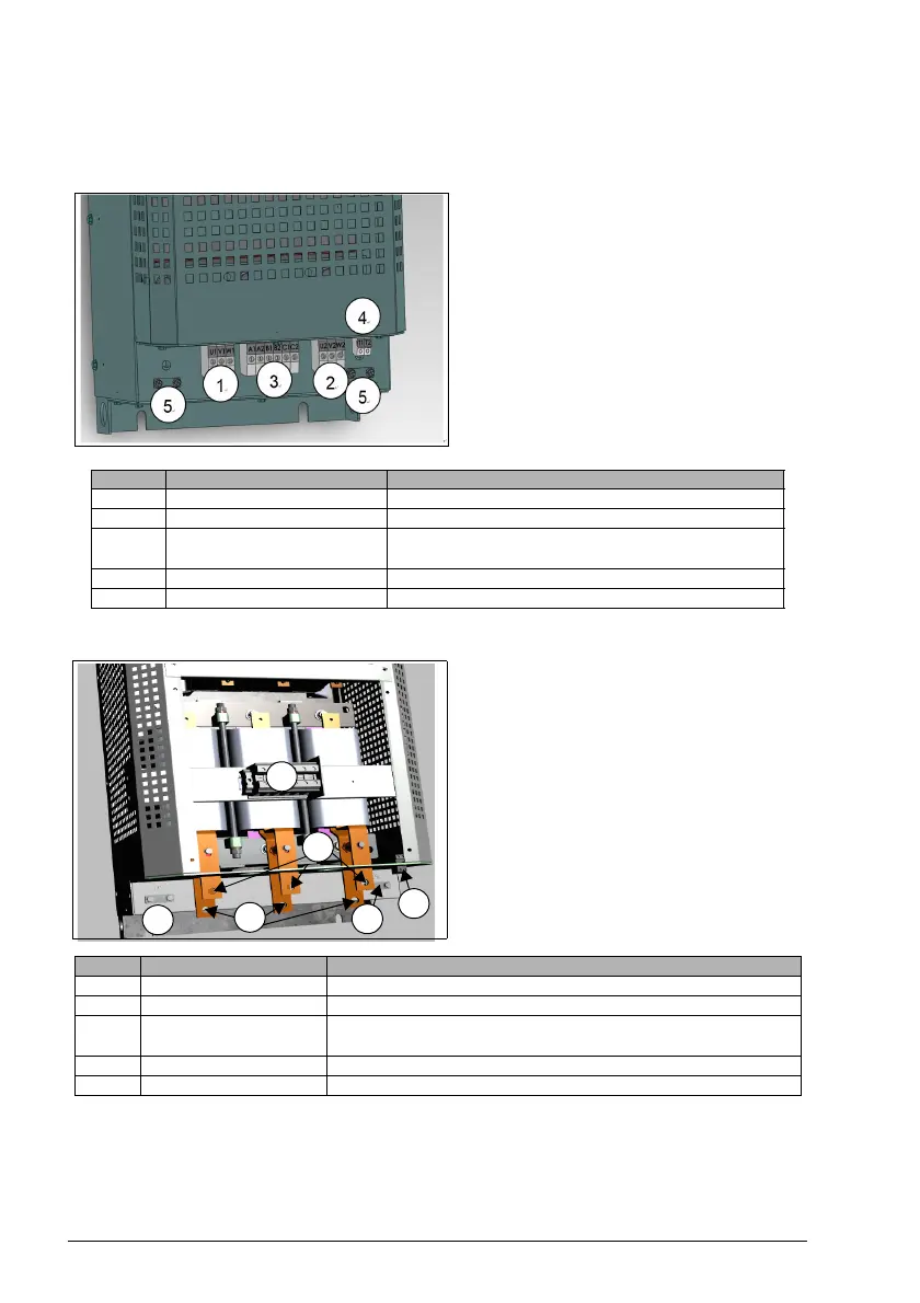
S1...S4
S5...S6
*For the use of bypassing the filter branch, after removing the short wiring of A1-A2, B1-B2, and C1-C2,
the user selects the appropriate control contactor according to the I
filter current value in the selection
information.
*Overheating protection terminals T1- T2 can be connected to the frequency converter as overheating
protection signals. In the normal state, it is normally closed. When the temperature limit of the
overheat protection is reached, the state will turn to off.
No. Terminal No. Description
1 U1/V1/W1 PIHF filter input terminal
2 U2/V2/W2 PIHF filter output terminal
3 A1/B1/C1/A2/B2/C2
PIHF filter loop control terminal (external contactor
control)
4 T1/T2 Overheat protection switch terminal
5 Protective earthing
No. Terminal No. Description
1 U1/V1/W1 PIHF filter input terminal
2 U2/V2/W2 PIHF filter output terminal
3 A1/B1/C1/A2/B2/C2
Filter branch bypass control terminal of PIHF filter (external
contactor control)
4 T1/T2 Overheat protection switch terminal
5 Protective earthing

 Loading...