I.L. 41-201.2G
3
TYPE CV FREQUENCY
COMPENSATED VOLTAGE RELAY
3.2.2 Trip Circuit Constants
Indicating Contactor 0.2 amp. Tap, 6.5 ohms
Switch dc resistance
2 amp. tap, 0.15 ohms
dc resistance
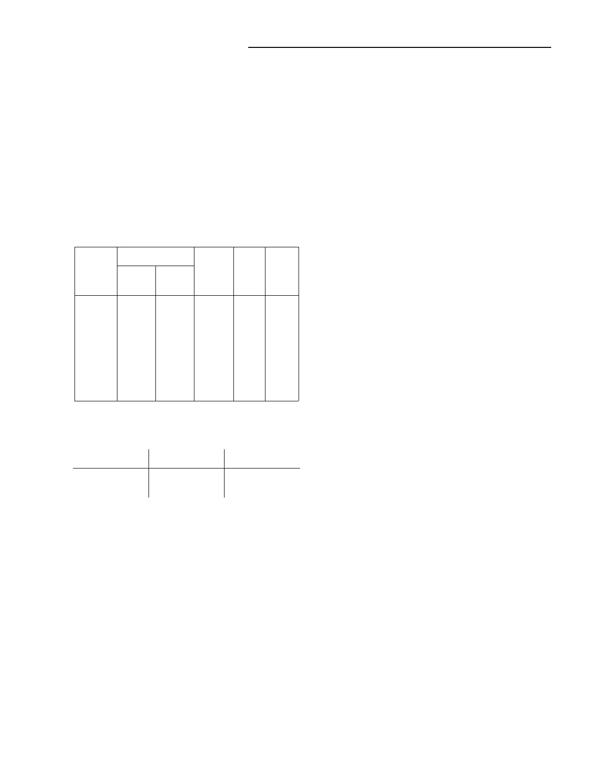
4.0 ENERGY REQUIREMENTS
The burdens of the CV-21, CV-22, CV-24, CV-25,
CV-26, CV-27 relays at rated voltage are shown in
Table A.
The burden of the IIV (when used) is in addition to
the above burdens and is as follows:
5.0 SETTINGS
5.1 CV UNIT
The setting of the CV unit can be defined either by
tap setting and time-dial position or by tap setting
and a specific time of operation at some percentage
of tap value voltage (e.g., on CV-24 120 tap setting, 2
times dial position or 120 tap setting, 12 seconds at
140 percent of tap value voltage).
To provide selective circuit breaker operation, a minimum
coordinating time of 0.3 seconds plus circuit breaker time
is recommended between the relay being set and the
relays with which coordination is to be effected.
The connector screw on the terminal plate above the
time dial connects various turns of the operating coil.
By placing this screw in the various terminal plate
holes, the relay will just close its contacts at the cor-
responding voltage of 55-64-70-82-93-105-120-140
volts or as marked on the terminal plate.
The nylon screw on the terminal plate holds the tap
plate in position when taps are being changed. To
use the position on the terminal plate in which the
nylon screw is used, remove the nylon screw and
place it in one of the unused holes. Then remove the
tap screw and insert it in the terminal plate hole.
5.1.1 Instantaneous Reclosing
The factory adjustment of the voltage unit contacts
follow. Where circuit breaker reclosing will be initi-
ated immediately after a trip by the overvoltage con-
tact, the time of the opening of the contacts should
be a minimum. This condition is obtained by loosen-
ing the stationary contact mounting screw, removing
the contact plate and then replacing the plate with
the bent end resting against the contact spring.
For double trip relays, the upper stationary contact is
adjusted such that the contact rests solidly against
the back stop. The lower stationary contact is then
adjusted such that both stationary contacts make
contact simultaneously with their respective moving
contact.
5.2 INSTANTANEOUS INDICATING VOLTAGE
SWITCH (IIV)
The adjustable resistor must be adjusted for the
desired pickup voltage.
5.3 INDICATING CONTACTOR SWITCH (ICS)
Only one setting is required on the ICS unit; that is,
the selection of the 0.2 to 2.0 ampere tap setting.
This selection is made by connecting lead located in
front of the tap block to the desired setting by means
of the connecting screws.
6.0 INSTALLATION
The relays should be mounted on switchboard pan-
els or their equivalent in a location free from dirt,
moisture, excessive vibration and heat. Mount the
relay vertically by means of the rear mounting stud or
studs for the type FT case projection case or by
means of the four mounting holes on the flange for
the semi-flush type FT case. Either the stud or the
mounting screws may be utilized for grounding the
relay. External toothed washers are provided for use
Table A:
Rated
voltage
TAPS
Volt -
Amps.
Power
Factor Watts
120 Volt
Relay
240 Volt
Relay
120 or
240 Volts
55
64
470
82
93
105
120
140
110
128
140
164
186
210
240
280
14.38
10.38
8.35
6.00
4.66
3.64
2.77
2.04
.44
.41
.39
.37
.35
.34
.33
.31
6.3
4.23
3.26
2.23
1.63
1.25
.92
.63
Setting Voltage Applied Burden
120 volts
200 volts
120 volts
200 volts
2.0 V.A.
3.0 V.A.
 Loading...


