41-223N CVQ Relay
4
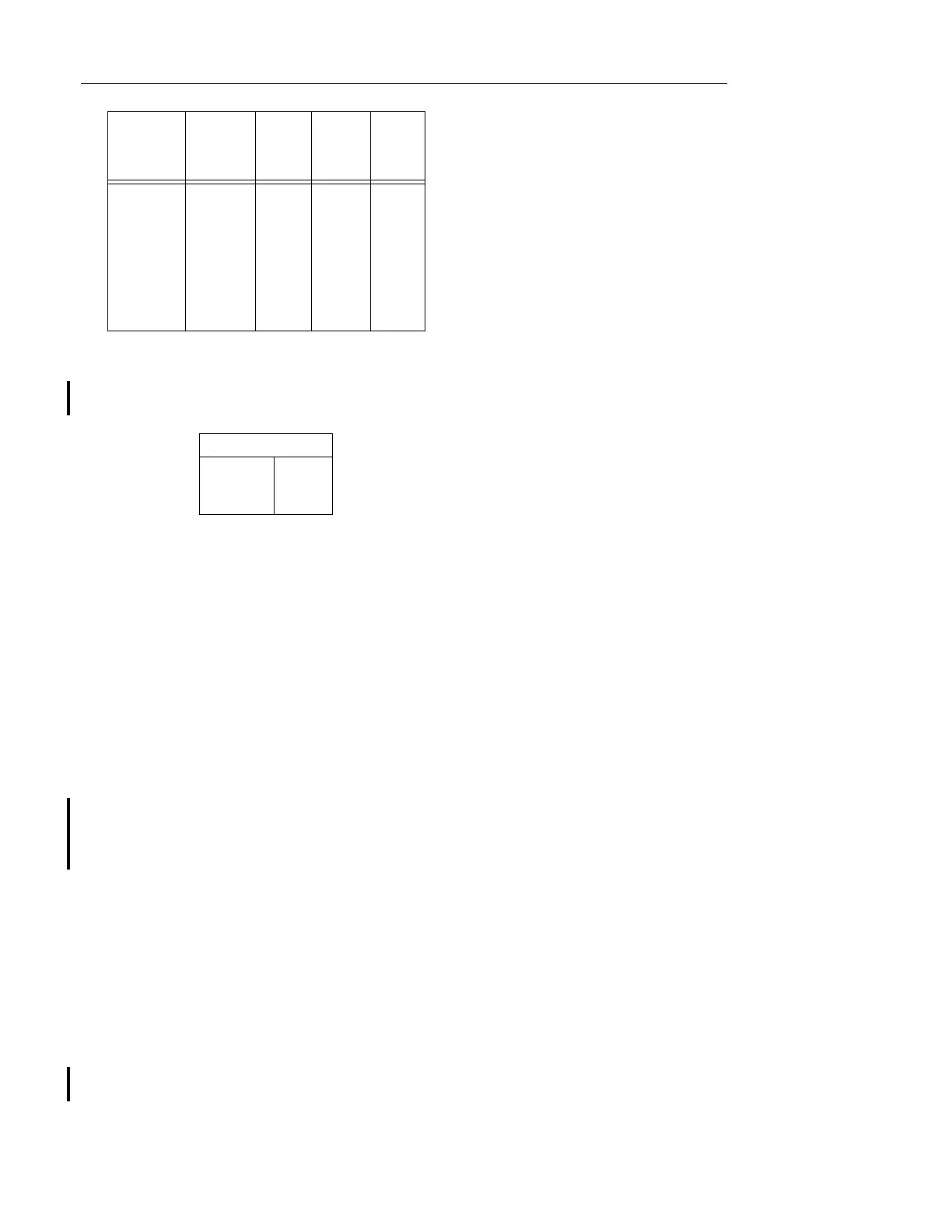
The burden of the negative sequence filter at rated
voltage is as follows:
5.0 SETTINGS
5.1 POLAR UNIT
The relay will be shipped adjusted for 5% negative
sequence sensitivity. Other settings may be made as
indicated under Section 8, “
Calibration
”.
5.2 CV UNIT
The setting of the CV unit can be defined either by
tap setting and time dial position; or by tap setting
and a specific time of operation at some percentage
of tap value voltage (e.g. on CV-7 120 volt tap setting
and 2 time dial position; or 120 volt tap setting and
1.8 seconds at 140% of tap value voltage). See fig-
ure 3 on page 8.
To provide selective circuit breaker operation, a mini-
mum coordinating time of 0.3 seconds plus circuit
breaker time is recommended between the relay
being set and the relays with which coordination is to
be effected.
The connector screw on the terminal plate above the
time dial connects various turns of the operating coil.
By placing this screw in the various terminal plate
holes, the relay will just close its front contacts at the
corresponding tap value of 55-64-70-82-93-105-120-
140 volts or as marked on the terminal plate.
The nylon screw on the terminal plate holds the tap
plate in position when taps are being changed. To
use the position on the terminal plate in which the
nylon screw is used, remove the nylon screw and
place it in one of the unused holes. Then remove the
tap screw and insert it in the terminal plate hole.
5.3 MOTOR PROTECTION SETTINGS
For motor protection a tap setting of 75 to 85% of
normal line to line voltages and a time dial setting of
6 or more should be satisfactory for protecting the
motor and overriding voltage variations for which trip-
ping is not desired.
5.4 NEGATIVE SEQUENCE FILTER
No setting required.
5.5 INDICATING CONTACTOR SWITCH (ICS)
The only setting required on the ICS unit is the
selection of the 0.2 or 2.0 ampere tap setting. This
selection is made by connecting the lead located in
the front of the tap block to the desired setting by
means of the connecting screw. The 0.2 ampere
setting is recommended where an auxiliary relay is
to be operated and the 2.0 ampere setting is recom-
mended where direct tripping of a circuit breaker is to
be accomplished.
5.6 RESISTOR (FOR TELEPHONE RELAY)
The relay is shipped with resistor in series with tele-
phone relay for 125 Vdc operation. For 48 Vdc oper-
ation this resistor is to be shorted.
6.0 INSTALLATION
The relays should be mounted on switchboard pan-
els or their equivalent in a location free from dirt,
moisture, excessive vibration and heat. Mount the
relay vertically by means of the rear mounting stud or
studs for the type FT projection case or by means of
the four mounting holes on the flange for the semi-
flush type FT case. Either the stud or the mounting
screws may be utilized for grounding the relay. Exter-
nal toothed washers are provided for use in the loca-
tions shown on the outline and drilling plan to
facilitate making a good electrical connection
between the relay case, its mounting screws or
studs, and the relay panel. Ground Wires are affixed
to the mounting screws or studs as required for
poorly grounded or insulating panels. Other electrical
Rated
a
Voltage
Taps
120 Volt
Relay
Volt
Amps
Power
Factor Watts
120 Volts
55
64
70
82
93
105
120
140
10.0
7.0
5.8
4.0
3.1
2.4
1.8
1.3
.38
.35
.34
.33
.31
.29
.28
.26
3.8
2.5
2.0
1.3
1.0
.7
.5
.3
a.
These relays will continuously withstand either 110% of
rated voltage or tap value voltage, whichever is higher
.
Volt Amperes
Phase 1
Phase 2
Phase 3
58.4
10.5
52.2
 Loading...


