8
Operation
indicators
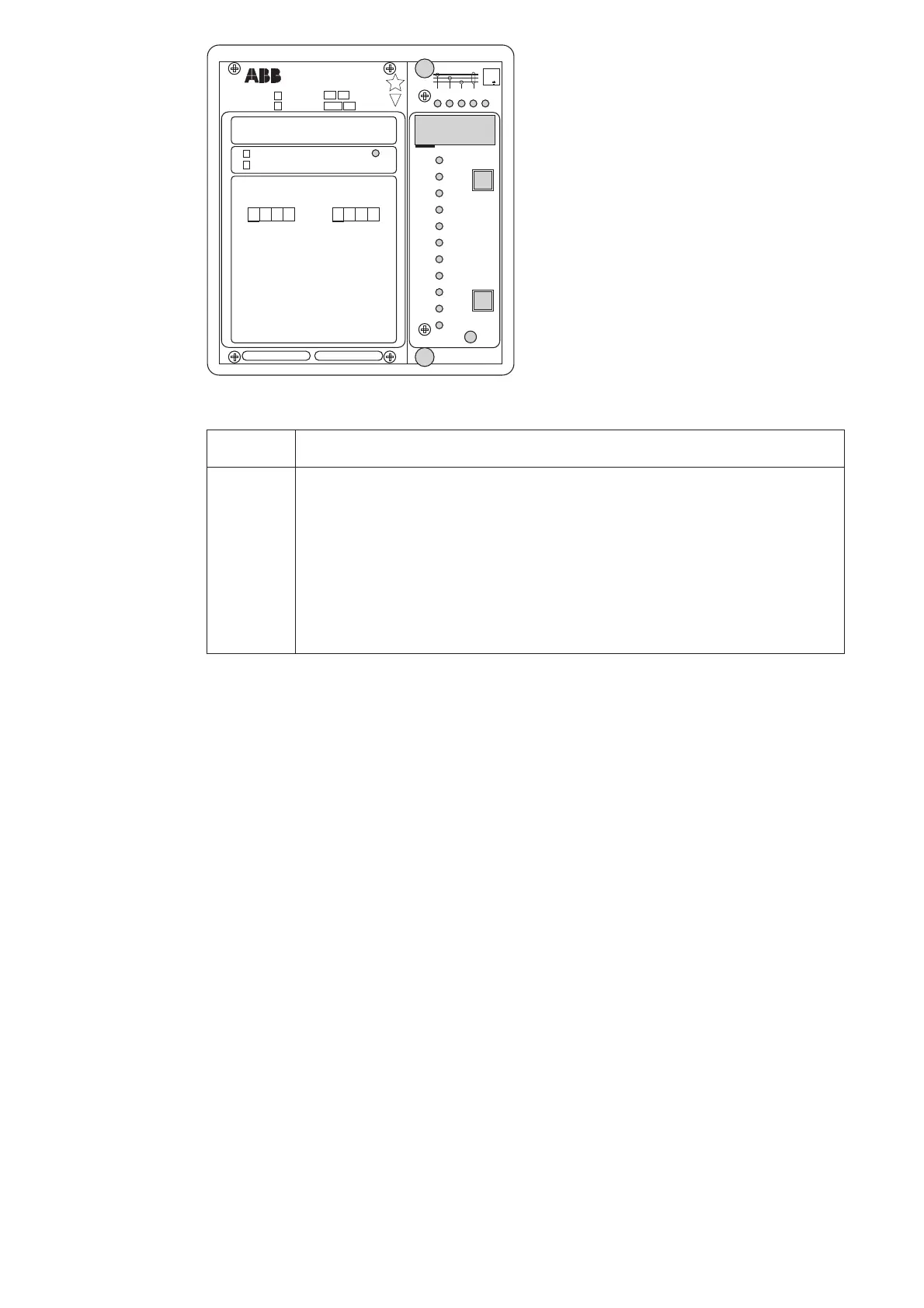
A) The operation indicator TRIP is switched
on when one of the protective stages operate.
When the protective stage resets, the red indi-
cator remains alight.
B) If the display is dark when one of the pro-
tective stages I>, I>>, I
0
> or I
0
>> call for a trip-
ping, the faulty phase or the neutral path is in-
dicated with a yellow LED. If, for instance, the
TRIP indicator glows red, and the indicators
I
L1
and I
L2
at the same time are illuminated,
overcurrent has occurred on phase L1 and L2.
C) Besides being a code number at data presen-
tation, the leftmost red digit or the display serves
as a visual function indicator. A function indi-
cator is recognized by the fact that the red digit
alone is switched on. The following table named
OPERATION IND. is a key to the function
code numbers used.
Ser.No.
SPAJ 142 C
aux
SPCJ 4D29
REGISTERS
OPER.IND.
0000
0
1
2
3
4
5
6
7
8
1
2
3
4
5
6
7
8
>
START
>
TRIP
>
>
TRIP
>
>
START
>
o
START
>
>
o
START
>
o
TRIP
>
>
o
TRIP
9
CBFP
9
0086A
I
I
I
I
I
I
I
I
80...265V
~
–
18...80V
–
2
5
U
f
n
= 50Hz
60Hz
RS 611 008 -
[
SGR
SGB
SGF
SPCJ 4D29
TRIP
PROGRAM
RESET
STEP
L1 L2 L3
0
IRF
3
>
I
I
I
II
I
>
n
I
I
/
k
s
>
t
]
n
>
>
I
I
/
s
>
>
[]
t
s
>
k
[]
t
n
0
>
I
I
/
s
>
>
o
t
[]
n
>
>
o
I
/
I
0012A
0
0
n
=
n
=
I
(
)
I
(
)
o
I
I
5A1A
1A0.2A
n
/
L3
n
/
L1
n
/
L2
max
(15min)
on
/
%
)(
>
%
)(
>>
()
>
o
%
(
o
)
%
>>
t
t
t
t
[]
[]
[]
[]
I
I
I
I
I
I
I
I
I
I
I
I
I
n
I
/
Indication Explanation
1 I> START = The low-set stage I> of the overcurrent unit has started
2 I> TRIP = The low-set stage I> of the overcurrent unit has tripped
3 I>> START = The high-set stage I>> of the overcurrent unit has started
4 I>> TRIP = The high-set stage I>> of the overcurrent unit has tripped
5I
0
> START = The low-set stage I
0
> of the earth-fault unit has started
6I
0
> TRIP = The low-set stage I
0
> of the earth-fault unit has tripped
7I
0
>> START = The high-set stage I
0
>> of the earth-fault unit has started
8I
0
>> TRIP = The high-set stage I
0
>> of the earth-fault unit has tripped
9 CBFP = Circuit Breaker Failure Protection has operated
D) The TRIP indications persist when the pro-
tective stage returns to normal. The indicator is
reset by pushing the RESET/STEP push-button.
Further, the indicators may be reset via the ex-
ternal control input 10-11 by switching a con-
trol voltage to the input, provided that the
microswitch SGB/8 is in position 1.
The basic protective relay functions are not de-
pending on the state of the operation indica-
tors, reset or non-reset. The relay is permanently
operative.
If a protective stage starts, but no tripping oc-
curs because the energizing quantity goes be-
low the starting level before the delay circuit
times out, the starting indicators are normally
automatically switched off. However, by means
of the switches SGF2/1…4 the starting indica-
tions may be made persistant which means that
they are to be reset by pushing the RESET/
STEP push-button.
The persistent indications are obtained through
the following programming.
Switch SGF2/1 = 1
Starting indication on I> persistent
Switch SGF2/2 = 1
Starting indication on I>> persistent
Switch SGF2/3 = 1
Starting indication on I
0
> persistent
Switch SGF2/4 = 1
Starting indication on I
0
>> persistent
On delivery from the factory the switches SGF2/
1…4 have the preset configuration 0.
E) Shortly after the internal self-supervision sys-
tem has detected a permanent relay fault the red
IRF indicator is switched on and the output re-
lay of the self-supervision system operates. Fur-
ther, in most fault situations a autodiagnostic fault
code is shown in the display. The fault code is
composed of a red figure 1 and a green code
number which indicates what may be the fault
type.The fault code can not be reset as long as
the fault persists. When a fault code appears on
the display, the code number should be recorded
on a piece of paper and given to the authorized
repair shop when overhaul is ordered.

 Loading...


