8
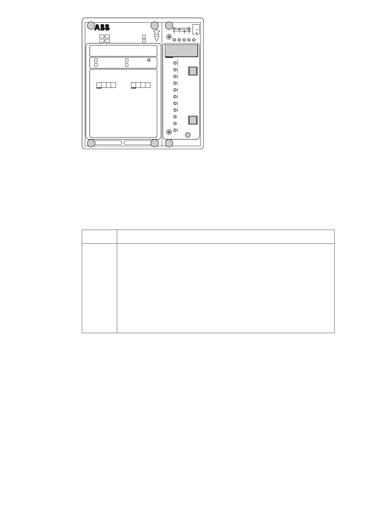
Operation
indicators
B) If the display is dark when one of the protec-
tion stages I>, I>> or I
0
> operates, the faulty
phase or the neutral path is indicated with a
yellow LED. If, for instance, the TRIP indi-
cator glows red, and the indicators I
L1
and
I
L2
at the same time are illuminated, over-
current has occurred on phase L1 and L2.
C) Besides being a code number at data presen-
tation, the leftmost red digit in the display
serves as a visual operation indicator. An
operation indicator is recognized by the fact
that the red digit alone is switched on. Nor-
mally the first event to appear is indicated.
For the thermal unit, however, a prior alarm
signal is later replaced by the trip indication,
if tripping is carried out. In order to enable
reading of actual thermal levels etc., it is
possible to acknowledge the indication of
the thermal unit while the unit is still acti-
vated. The same applies to a signalling earth-
fault. In these cases the indications are memo-
rized and reappear when the display is dark.
All operation indicators are automatically
reset when the motor is restarted. The fol-
lowing table, named OPERATION IND.
on the relay front panel, is a key to the
operation indicator code numbers used.
SPCJ 4D34
TRIP
PROGRAM
RESET
STEP
L1 L2 L3
o
IRF
I
II
I
956
SGR 1
SGR 2
SGB
SGF
kc
θ
<
I
I
%
[]
t
Σ
s
[
]
si
<
t
s
[
]
∆
t
Σ
s/h
[
]
s
[]
t
∆
L
I
I
%
[]
∆
o
t
s
[
]
>
>
t
s
[
]
n
I
I
/
>
>
n
s
I
I
/
s
t
s
[
]
n
θ
I
I
/
6x
t
s
[
]
p
[
]
%
θ
a
[
]
%
θ
i
[
]
%
o
I
n
I
[
]
%
s
3
I
>
>
3
I
RS 641 Ser.No.
SPAM 150 C
U
aux
SPCJ 4D34
REGISTERS
OPER.IND.
0000
0
1
2
3
4
5
6
7
8
n
/
L3
n
/
L1
n
/
L2
1
2
3
4
5
6
7
8
>
>
o
<
2
5
9
EXT.TRIP
9
t
%
[
]
%
θ
[]
955D
I
I
I
I
I
I
I
I
I
I
I
80...265V
18...80V
–
n
=
(
)
I
I
5A1A
n
=
I
(
)
o
I
5A1A
o
I
n
I
∆
2
θ
a
θ
>
θ
t
θ
>
θ
t
i
i
+
t
Σ
si
EINH
+
I
∆
θ
m
%
[]
min
[ ]
I
2
t
%
[]
%
[]
L
I
t
I
2
s
s
–
~
NO
NC
f
n
= 50Hz
60Hz
A) The operation indicator TRIP is lit when
one of the protection stages operates. When
the protection stage resets, the red indicator
remains alight.
Indication Explanation
1 θ > θ
a
= The thermal level has exceeded the set prior alarm level
2 θ > θ
t
= The thermal unit has tripped
3 θ > θ
i
, ∑t
si
, = The thermal restart inhibit level is exceeded, the startup time
EINH counter is full or the external inhibit signal is active
4 I>> = The high-set stage of the overcurrent unit has tripped
5 ∆I = The unbalance/incorrect phase sequence protection unit has
tripped
6I
2
x t = The start-up stall protection unit has tripped
7I
0
= The earth-fault unit has tripped
8 I< = The undercurrent unit has tripped
9 EXT.TRIP = An external tripping has been carried out
D) The TRIP indications persist when the pro-
tective stage returns to normal. The indica-
tor is reset by pushing the RESET/STEP
push-button. A restart of the motor auto-
matically resets the operation indications.
Further, the indicators may be reset via the
external control input 10-11 by applying a
control voltage to the input, provided that
the switch SGB/6 is in position 1.
The basic protective relay functions are not
depending on the state of the operation
indicators, i.e. reset or non-reset. The relay is
permanently operative.
E) In two minutes after the internal self-super-
vision system has detected a permanent relay
fault the red IRF indicator is lit and the
output relay of the self-supervision system
operates. Further, in most fault situations an
autodiagnostic fault code is shown in the
display. The fault code is composed of a red
figure 1 and a green code number, which
indicates the fault type. The fault code can
not be reset as long as the fault persists.
When a fault code appears on the display, the
code number should be recorded on a piece
of paper and given to the authorized repair
shop, when overhaul is ordered.
 Loading...


