CMT 1000 commissioning and maintenance tool
You can set the parameters of the AVR with the CMT 1000 commissioning and
maintenance tool PC application for Microsoft Windows. CMT 1000 connects to
the AVR through the USB port or Ethernet port. An Ethernet connection permits
access to the AVR from remote locations. For more information on CMT 1000,
refer to the
User Manual
.
Operation
The AVR is controlled by analog and digital I/Os. You can also use control signals
by remote access over MODBUS.
Use CMT 1000 only to set parameters and operation and not as an operator
interface.
For detailed information on operation, refer to the
User Manual
.
Technical data
1) 3-phase power supply and an external 1 mF capacitor required to operate
UNITROL 1020 between 15 A and 20 A nominal excitation current.
2) Machine voltage measurement above 250 V AC requires the connection of the
machine star point to earth (PE).
UL ratings
To use the AVR in a UL compliant way, consider the following:
• Electrical ratings for 55 °C surrounding air temperature
• Maximum surrounding air temperature 55 °C – 70 °C with derating as
follows
• UNITROL 1010 maximum output capability: 5 A/150 V
• UNITROL 1020 maximum output capability: 10 A/150 V
• Use only 60/75 °C rated wires
• For use in a Pollution Degree 2 Environment
Grounding conductor terminal is green-colored or plainly identified with “G”,
“GRD”, “GND”, “GRND”, “Ground”, “Grounding” or IEC Publication 417, Symbol
5019.
Excitation inputs PWR L1, PWR L2 and PWR L3 must be protected by a circuit
breaker rated at 480Y/277 V AC, maximum 15 A when supplied from an AC
source or listed class RK5 fuse rated at 300 V DC, maximum 15 A when supplied
from a DC source.
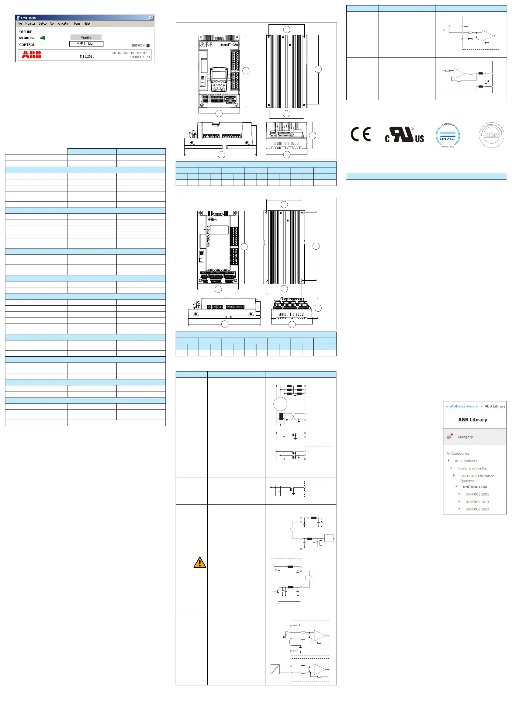
Dimensions
UNITROL 1020
UNITROL 1010
Device connections
Certifications
The applicable certifications are shown on the product’s type label.
Related documents
Support information
ABB Switzerland Ltd
Static Excitation Systems, Voltage Regulators and Synchronizing Equipment
CH-5300 Turgi / Switzerland
Internet: http://www.abb.com/unitrol
24 h hotline for urgent service inquiries: +41 844 845 845
E-mail contact for questions and support:
unitrol1000.supportline@ch.abb.com
Documentation, software and tools
You can get access to the latest documentation, software and tools for the AVR
on the myABB business portal.
To get access:
1. Go to https://myportal.abb.com in your web browser.
2. Select Log In.
• If you have an ABB account, you can sign in with your email and
password.
• If you do not have an ABB account, refer to How to register to the
myABB business portal.
3. After you log in, the myABB dashboard opens.
4. On the myABB dashboard, find the myExcitation widget. For information on
how to register to the myExcitation widget, refer to How to register to the
myExcitation widget.
5. In the myExcitation widget in the myABB business portal, select GO TO ABB
LIBRARY.
6. ABB Library opens.
7. In the left-hand menu, select Category >
ABB products > Power Electronics >
UNITROL Excitation Systems >
UNITROL 1000 > UNITROL 1010 or
UNITROL 1020.
8. Select your documentation. You can
search for documents by categories and
by document kind.
9. You can also download the documents to
your computer.
How to register to the myABB business
portal:
1. Select Sign up below the LOGIN button.
2. Fill in the registration form.
3. Select Sign up.
4. ABB sends you an email for activation of
your ABB account.
5. In the email, select ACTIVATE ACCOUNT.
6. You now have an access to the myABB business portal.
How to register to the myExcitation widget:
1. In the myExcitation widget in the myABB business portal, select GET
ACCESS.
2. Fill in the registration form.
After registration, you can get access to UNITROL 1000 series documents and
tools on the ABB Library.
UNITROL 1010 UNITROL 1020
Local control panel No Yes
Ingress protection rating IP20 IP20
Power electronic output
AC nominal input voltage 0 to 250 V AC 0 to 250 V AC
Frequency 25 to 600 Hz 25 to 600 Hz
DC nominal input voltage 0 to 300 V DC 0 to 300 V DC
Maximum peak input voltage
(non-sinusoidal)
420 V
P
420 V
P
Minimum required start voltage N/A N/A
Auxiliary supply (controller input)
AC nominal input voltage 3-phase 9 to 250 V AC 9 to 250 V AC
AC nominal input voltage 1-phase 16 to 250 V AC 16 to 250 V AC
Frequency 40 to 600 Hz 40 to 600 Hz
DC nominal input voltage 18 to 300 V DC 18 to 300 V DC
Maximum peak input voltage
(non-sinusoidal)
420 V
P
420 V
P
Excitation output
Continuous current at 55 °C 10 A DC 15 A DC
20 A DC
1)
Overload current for 10 seconds at
55 °C
25 A DC 38 A DC
Exciter current measurements
Full range 0 to 38 A 0 to 38 A
Accuracy / Resolution < 1% / < 100 mA < 1% / < 100 mA
Machine and net measurements
Machine voltage, 1-, 2-, or 3-phase Up to 500 V AC
2)
Up to 500 V AC
2)
Machine current, 1-phase 1 to 5 A AC 1 to 5 A AC
Network voltage, 1-phase Up to 500 V AC Up to 500 V AC
Frequency range 10 to 150 Hz 10 to 150 Hz
Accuracy (-40 °C to 70 °C / at
25 °C
)
±1% / 0.1% ±1% / 0.1%
Voltage regulation
AVR response time (3-phase / 1-
phase measurement)
< 20 ms / < 50 ms < 20 ms / < 50 ms
PwM limitation 0.5 to 99% 0.5 to 99%
Digital inputs and outputs
Numbers of digital I/Os
(inputs / in or out / output)
4 / 8 / 0 4 / 8 / 0
Digital I/O voltage 24 V 24 V
Analog inputs and outputs
Number of analog inputs/outputs 3 / 2 3 / 2
Analog I/O range ±10 V ±10 V
Communication interfaces
Ethernet (cable length < 100 m) 10 / 100 MBit/s 10 / 100 MBit/s
USB version (use the provided red
USB cable only)
1.0, 1.1, 2.0 1.0, 1.1, 2.0
CAN (cable length < 3 m) Only for connections between UNITROL 1000 devices.
Dimensions and weights
D1 W1 W2 W3 H1 H2 Weight
mm in mm in mm in mm in mm in mm in kg lb
111 4.3 170 6.7 143.5 5.6 147.5 5.8 302 11.9 280 11.0 3.8 8.4
Dimensions and weights
D1 W1 W2 W3 H1 H2 Weight
mm in mm in mm in mm in mm in mm in kg lb
85 3.3 170 6.7 143.5 5.6 147.5 5.8 302 11.9 280 11.0 2.8 6.2
Terminal Signal Circuit
7 = ML1
6 = ML2
5 = ML3
2 = MC2+
1 = MC2-
7 = ML1
5 = ML3
7 = ML1
6 = ML2
5 = ML3
Machine Voltage three-phase
U
M
• Machine L1
• Machine L2
• Machine L3
Warning: If Um > 250 V AC, then
the star point must be
connected to PE.
Machine Current single-phase
I
M2
• Machine Current +
• Machine Current -
Machine Voltage single-phase
U
M
• Main L1
• Main L3
Machine Voltage three-phase
with ground U
M
• Machine L1
• Machine L2
• Machine L3
1) You must ground PT & CTs.
4 = NW1
3 = NW3
Line voltage measurement
single-phase U
NET
Network L1
Network L3
1) You must ground PT & CTs.
37 = D1
36 = D2
35 = D3
34 = D4
31 = D5
30 = D6
29 = D7
28 = D8
39 = V1
38 = V2
33 = V3
32 = V4
20 = G2
21 = G1
Digital input/output
Digital input/output 1
Digital input/output 2
Digital input/output 3
Digital input/output 4
Digital input/output 5
Digital input/output 6
Digital input/output 7
Digital input/output 8
CAUTION!
When configured as outputs, do
not connecte DIO1…DIO8
directly to the 24 V supply
(causes a short circuit via
internal transistor).
24 V power
24 V power
24 V power
24 V power
GND
GND
53 = AI1, 52 = BI1
51 = AI2, 50 = BI2
49 = AI3, 48 = BI3
47 = ARP
45 = ARN
BRP = 46
BRN = 44
Analog Inputs
AIx/BIx
Signal bandwidth 100 Hz
+10 V pos Ref
-10 V neg Ref
GND Positive Reference
GND Negative Reference
R = 10 k
Ω (±5 V input range)
D1
W1
W2
H1
H2
H1
W1
W3
D1
W1
W2
H1
H2
H1
W1
W3
ML1
ML2
ML3
ML1
ML2
ML3
L1 L2 L3
ML1
ML3
MC2+
MC2-
SM
IM2
External
External
External
max. 500 / 0.2 VA
max. 500 / 0.2 VA
max. 500 / 0.2 VA
1A / 5 A
0.1 VA
1)
1)
1)
1)
External
max. 500 / 0.2 VA
1)
24 V
24 V
ADC
2 k
V1
V2
G1
D1
V1
V2
D1
G1
max.
150 mA
20 ... 28 V
20 ... 28 V
External
External
AI1
+
-
R
BI1
+
-
+
-
BRP
10 V DC
47 k
100 k
10 k
100 k
47 k
4.7 k
4.7 k
max.
±10 V
ARN
AI1
BI1
-10 V DC
AGND
100 k
100 k
47 k
47 k
External
External
53 = AI1, 52 = BI1
51 = AI2, 50 = BI2
49 = AI3, 48 = BI3
Analog Inputs digitally assigned
AIx/BIx
43 = AO1
41 = AO2
42 = BO1
40 = BO2
Analog Outputs
AOx to BOx
(AGND = BO1, BO2)
Max. output current: 10 mA
Document Code
UNITROL® 1010 User Manual (English)
3BHS335648 E81
UNITROL® 1020 User Manual (English)
3BHS335648 E82
UNITROL® 1000 Control SW manual (English)
3BHS399489 E02
UNITROL® 1000 Commissioning instructions (English)
3BHS399489 E01
UN1000 Modbus Address table (English)
3BHS358281 E81
UN1000 Modbus Reference Manual (English)
3BHS358281 E80
UN1000 Railway Type Test Summary (English)
3BHS258571 E44
UN1000 Type Test Summary (English)
3BHS258571 E41
Release Notes HW/SW (English)
3BHS355555 E02
Terminal Signal Circuit
ARP
AI1
Ain
BI1
4.7 k
4.7 k
100 k
100 k
10 V DC
47 k
+
-
DNV•GL MaritimeCE marking cUL recognized SQS
3BHS335648 E02 Rev B 2020-12-08
© 2020 ABB Switzerland Ltd. All rights reserved.
 Loading...