STRUCTURE AND MODE OF ACTION 17
—
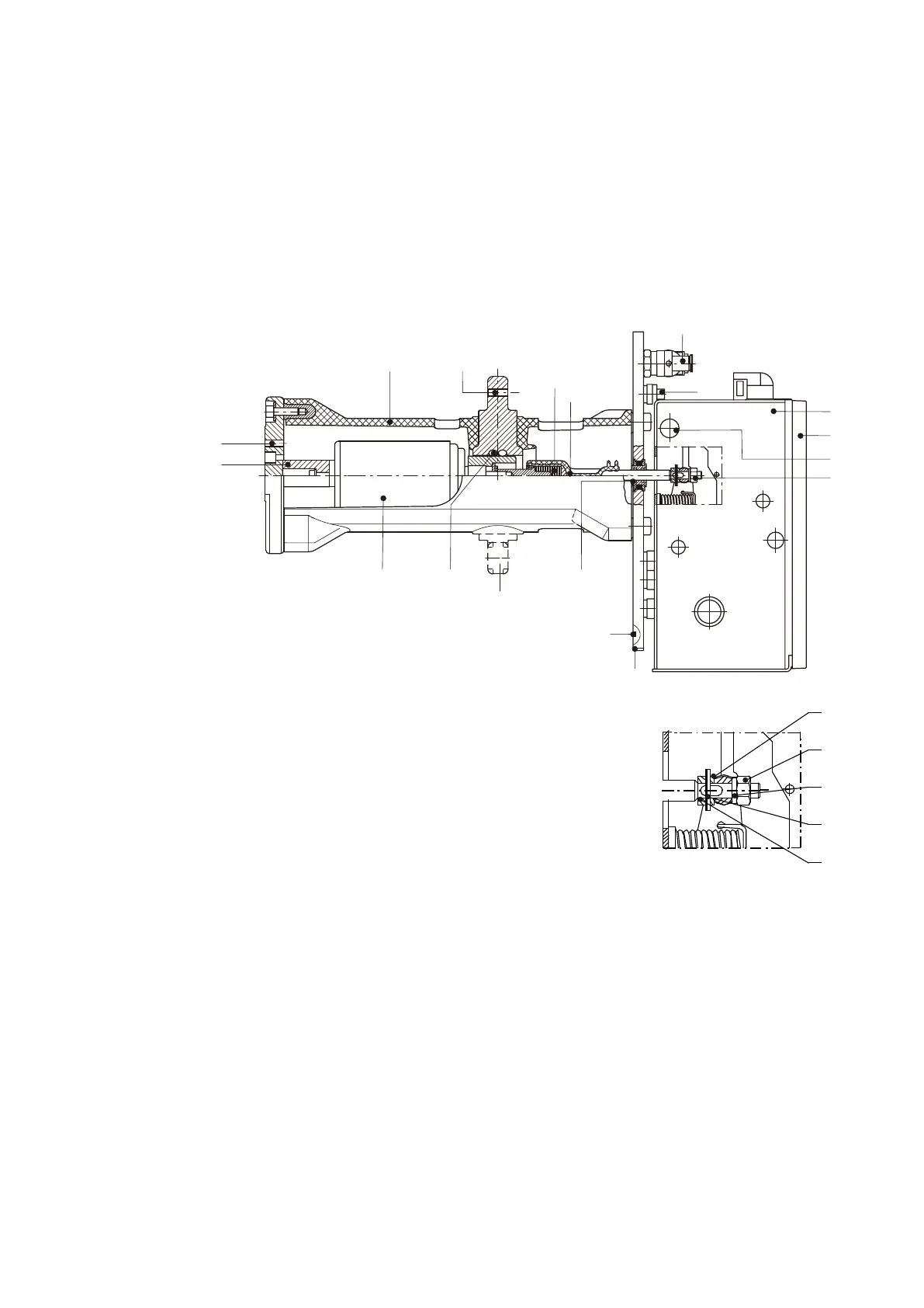
Figure 3/1: Sectional
view of a vacuum
circuit-breaker, type
VD4 X.
11
12
1)
16
17
13
35
15
14
1)
19
9.1
9
18
1.2
1.1
1
9.2
33
18
18.1
18.3
18.4
1) Busbar connection arranged above or below the breaker pole
depending on the switchgear system.
—
Figure 3/1
1 Circuit-breaker operating mechanism
1.1 Front plate
1.2 Bore for handling, both sides
9 Mounting plate
9.1 O-ring
9.2 Operating mechanism mounting
11 Insulating material pole tube
12 Breaker terminal
13 Front breaker terminal
14 Spiral spring contact
15 Vacuum interrupter
16 Contact force spring
17 Insulating push-rod
18 Lock nut
18.1 Spring washer
18.2 Retaining plate
18.3 Positioning plate
18.4 Washer
19 Gas-tight thrust bushing
33 Pressure sensor for circuit-breaker compartment
35 Adapter

 Loading...