Acer Service Manual
Chapter 5- TEST AND ADJUSTMENT
1. GENERAL POINTS
1.1 Test Equipment or Tool
1.1.1 Test pattern generator: PC or video pattern generator (Chroma-2326/2160/2130)
1.1.2 Color analyzer: Chroma-7120
1.1.3 Power meter: AC Source Chroma-6408
1.1.4 Electrical safety tester: Chroma (Zentech) 9032A
1.1.5 Auto shock fixture
1.1.6 Temperature and humidity sensor
1.1.7 DDC interface card and EDID file
1.2 Preset Test Pattern
1.2.1 Crosshatch (General-1)
1.2.2 Gray Bar (16 & 32 levels)
1.2.3 Full White
1.2.4 Aging (Burn-in) Pattern: full Green, Blue, White, Black and Red
1.3 AC input
All measurements mentioned hereafter are carried out at a normal mains voltage (90 - 264 V
AC
for the
model with full range power supply, unless otherwise stated)
1.4 Observation Distance
1.4.1 Observation distance from eyes to panel is defined as 50cm
1.4.2 Visual distance from instrument to panel is defined as 20cm
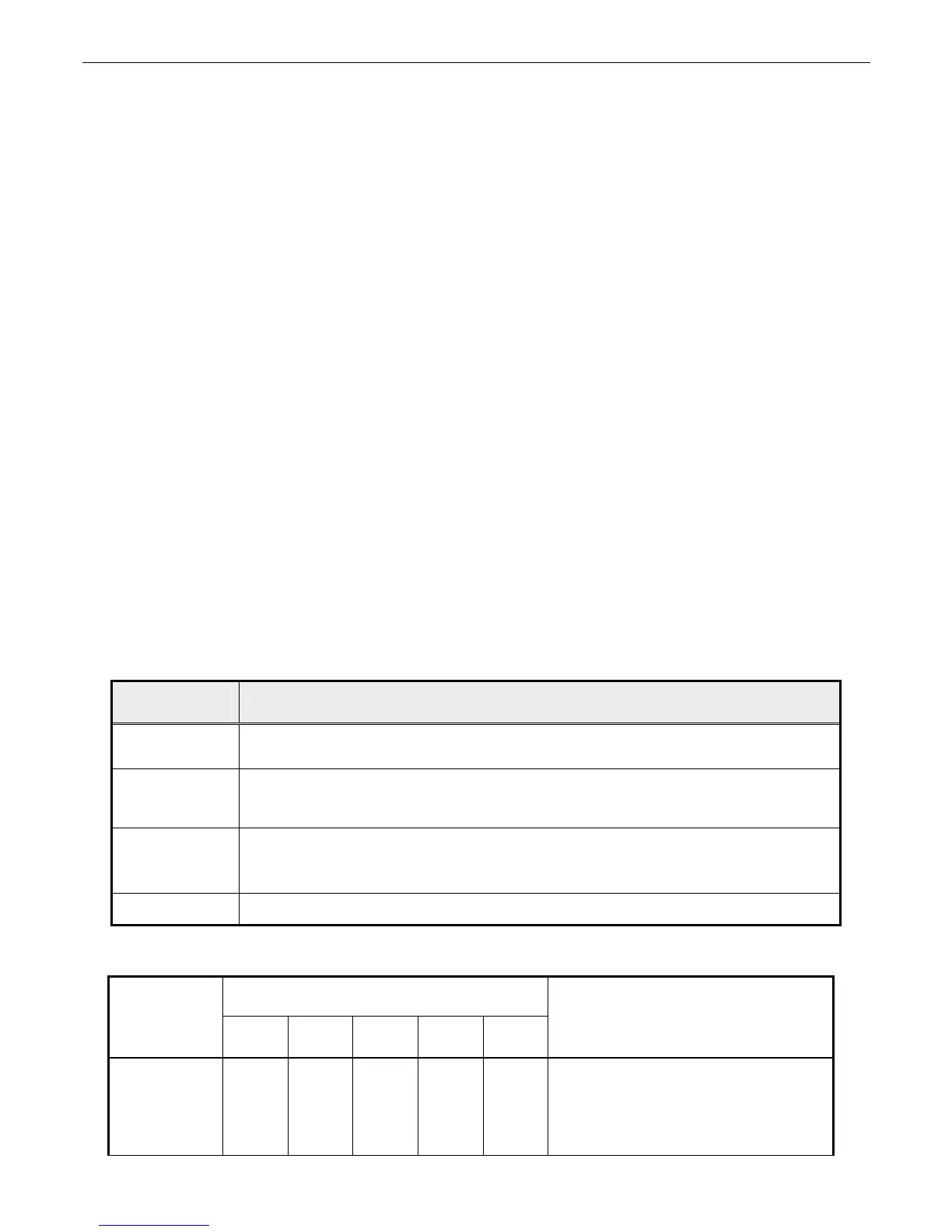
1.5 Key Function Description
1.5.1 Control buttons on the front bezel
CONTROL
KEY
KEYS FUNCTION
[AUTO]
A. When OSD un-displays, press [AUTO] to perform auto-adjustment
B. When OSD displays, press [AUTO] to return to previous level menu
[MENU]
A. When OSD isn’t shown on screen, press [MENU] to enter OSD interface
B. When OSD displays, press [MENU] to perform function of menu icon that is
highlight or enter next level menu
[►], [◄]
A. When “MENU OSD” displays, press these keys to change the contents of an
adjustment item, or change an adjustment value
B. When “MENU OSD” un-displays, press these keys no function
[POWER] Power on or power off the monitor
1.5.2 Hot Key Operation
HOT KEY OPERATION
FUNCTION
AUTO ◄ ► MENU POWE

 Loading...