12
Application Information
Installation Guide
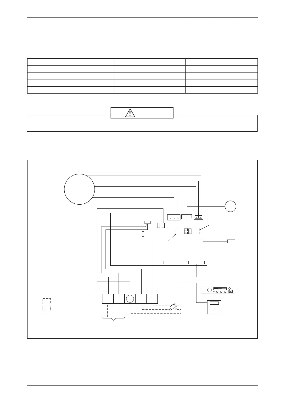
System Conguration
The standard controller board comes with a VALVE jumper and a HEAT jumper. The system can be
congured as the jumper selection listed below:
HEAT Jumper VALVE Jumper
Heatpump Mode & Valve Application √ √
Heatpump Mode & Valveless Application √ X
Cooling Mode & Valve Application X √
Cooling Mode & Valveless Application X X
√ Jumper Remained X Jumper Removed
Caution
Disconnect the power supply to the unit before attempting to connect the wiring
Valve, Heat and Fan Priority Setting
Model: AWM-JW
HEAT
VALVE
N
CN_FAN
CN_PGRM CN_WIR CN_DSP
VALVE HEAT
VALVE
CN_STP
CN_ID COIL
CN_FAN FB
L
BLACK (LIVE)
RED (FAN CAP)
WHITE (NEUTRAL)
Valve Jumper
Heat Jumper
WHITE
BROWN
BLACK
BLUE
BLUE
RED
G/Y
NOTATION
FM : FAN MOTOR
AS : AIR SWING MOTOR
TH1 : INDOOR COIL THERMISTOR
TH2 : ROOM THERMISTOR
-WITH JUMPER FOR HEAT PUMP
-WITHOUT JUMPER FOR COOLING ONLY
-WITH JUMPER FOR VALVE APPLICATION
FIELD WIRING
-WITHOUT JUMPER FOR VALVELESS APPLICATION
2/3 WAY VALVE
L
POWER
SUPPLY
TH2
TH1
DISPLAY BOARD
WIRED
CONTROLLER
(OPTIONAL)
N
E
VALVE
N1 N L
AS
FM
 Loading...