17
Modules Specifications
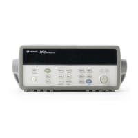
The Agilent 34970A accuracy specifications already
include the switching offset and reference junction
errors shown below. These errors are listed sepa-
rately for determining system error with external
measurement devices.
Up to three modules, in any combination, can be
inserted into a single mainframe. The 34970A’s
internal DMM connections are accessible only
through the 34901A, 34902A, and 34908A low-
frequency multiplexers.
On-module screw terminals accept wire sizes from
16 gage to 22 gage. Twenty-gage wire is recom-
mended for high channel count applications. The
34905A and 34906A RF Multiplexers use SMB
connectors. A standard set of (10) BNC-to-SMB
adapter cables is provided with each RF module
for convenient BNC connections.
Multiplexer Actuator Matrix RF Multiplexer Multifunction
34901A 34902A
[1]
34908A 34903A 34904A 34905A 34906A 34907A
General
Number of Channels 20 + 2 16 40 20 4 x 8 Dual 1 x 4 See page 22
2/4 wire 2/4 wire 1 wire SPDT 2 wire 50 Ω 75 Ω for module
Connects to Internal DMM • • • specifications
Scanning Speed 60 ch/s 250 ch/s 60 ch/s
Open/Close Speed 120/s 120/s 70/s 120/s 120/s 60/s
Input
Voltage (dc , ac rms)
[2]
300 V 300 V 300 V 300 V 300 V 42 V
Current (dc , ac rms) 1A 50mA 1A 1A 1A 0.7A
Power (W , VA) 50 W 2 W 50 W 50 W 50 W 20 W
DC Characteristics
Offset Voltage
[3]
< 3uV < 6uV < 3uV < 3uV < 3uV < 6uV
Initial Closed Channel R
[3]
< 1 Ω < 1 Ω < 1 Ω < 0.2 Ω < 1 Ω < 0.5 Ω
Isolation ch-ch, ch-earth > 10 G Ω > 10 G Ω > 10 G Ω > 10 G Ω > 10 G Ω > 1 G Ω
AC Characteristics
Bandwidth
[4]
10 MHz 10 MHz 10 MHz 10 MHz 10 MHz 2 GHz
[5]
2 GHz
[5]
Insertion Loss (dB) 10 MHz —————-0.1 -0.1
100 MHz —————-0.4 -0.4
500 MHz —————-0.6 -0.5
1 GHz—————-1 -1
1.5 GHz —————-1.2 -1.5
2 GHz—————-3 -2
SWR 10 MHz—————1.02 1.02
100 MHz —————1.05 1.05
500 MHz —————1.20 1.25
1 GHz—————1.20 1.40
1.5 GHz —————1.30 1.40
2 GHz—————1.40 2.00
ch-ch Cross Talk (dB)
[4]
10 MHz -45 -45 -18
[6]
-45 -33 -100 -85
100 MHz —————-85-75
500 MHz —————-65-65
1 GHz—————-55-50
1.5 GHz —————-45-40
2 GHz—————-35-35
Risetime < 300 ps
Signal Delay < 3 ns
Capacitance HI - LO < 50 pF < 50 pF < 50 pF < 10 pF < 50 pF < 20 pF
LO - Earth < 80 pF < 80 pF < 80 pF < 80 pF < 80 pF —
Volt-Hertz limit 10
8
10
8
10
8
10
8
10
8
10
10
Other
T/C Cold Junction Accuracy
[3]
(typical)
0.8°C 0.8°C 0.8°C
[8]
Switch Life No Load (typical) 100M 100M 100M 100M 100M 5M 5M
Rated Load (typical)
[7]
100k 100k 100k 100k 100k 100k 100k
Temperature Operating all cards — 0°C to 55°C
Storage all cards — -20°C to 70°C
Humidity (non-condensing) all cards — 40°C/80% RH
[1] Not recommended for connection to ac line without external transient suppression
[2] Channel-to-channel or channel-to-earth
[3] Errors included in DMM measurement accuracy specifications
[4] 50Ω source, 50Ω load
[5] Bandwidth direct to card SMB connectors
[6] Isolation within channel 1 to 20 or 21 to 40 banks is -40 dB
[7] Applies to resistive loads only
[8] Thermocouple measurements not recommended with 34908A
module due to common lo configuration

