13
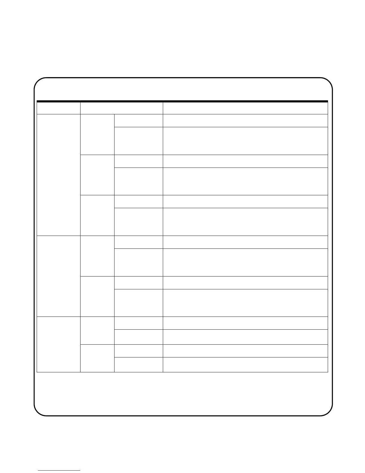
Trigger Menu Sub Menu Description
Pattern
Trigg er
More 1/3
page
Input 1 Logic To select input logic 1 as CH1 High or Low and CH2 High or Low
Input 1 Level To set trigger level for Manual, TTL, ECL or Set to 50%.
For manual adjustment, change the rigger level by turning rotary
switch
More 2/3
page
Input 2 Logic To select input logic 2 as CH1 High or Low and CH2 High or Low
Input 2 Level
To set trigger level for Manual, TTL, ECL or Set to 50%.
For manual adjustment, change the trigger level by turning rotary
switch
More 3/3
page
Gate
To set logic gate AND, OR, NAND or NOR
Condition
To select trigger condition to Shorter, Longer, Between or Non-
Between of a set value. To set the trigger value, turn and press the
rotary switch
Pulse Trigger More 1/2
page
Source To select channel source 1 or 2 for triggering
Level
To set trigger level for Manual, TTL, ECL or Set to 50%.
For manual adjustment, change the trigger level by turning rotary
switch
More 2/2
page
Polarity To set positive or negative polarity
Condition
To select trigger condition to Shorter, Longer, Between or Non-
Between of a set value. To set the trigger value, turn and press the
rotary switch
Video Trigger More 1/2
page
Standard To select video signal type: 625/PAL, SECAM or 525/NTSC
Source
To select channel source 1 or 2 for triggering
More 2/2
page
Even/Odd
To select trigger for odd or even field of the video signal
Line
To set the number of lines for the signal display

 Loading...


