GB 12
GB
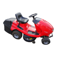
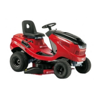
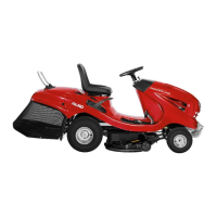
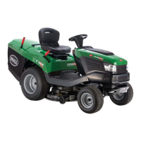
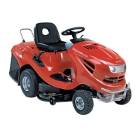
ASSEMBLY
The following assembly work must be carried out before the first
operation:
1. Installation of the wheels.
2. Installation of the steering wheel.
3. Installation of the driver's seat.
4. Assembly of the grass box
5. Fitting the grass box to the lawn tractor.
Attention!
Putting into operation (even test operation) before complete
assembly is strictly forbidden - dangers of accidents!
The information on directions (right, left, top etc.) for this appliance
are to be understood in the direction of travel looking from the
driver's seat.
The order of assembly steps is to be complied with, as otherwise
flawless function cannot be guaranteed.
Please note:
The figures stated to the left of the text, such as the
here, refer to the illustrations in the illustrated part at the front.
Front wheels:
Lock both front wheels.
Lift tractor slightly by bumper and pull to front wheel.
Push washer toward wheel rim.
Insert lock washer into shaft groove before washer and
press down.
2x lock washer dia. 15x29x1.5 - contained in screw/bolt
bag.
Fit cover cap.
Rear wheels:
Lock both rear wheels.
Move tractor to rear wheel until rear wheel is heard to strike
steering knuckle.
Wheel axle protrudes from rim.
O-ring Ø11 x 2.6 is fitted in the works -
(secures the parallel key).
Remove O-ring - do not re-use
Fit one washer
1x 19 mm dia. x 26 mm dia. and
1x 20 mm dia. x 42 mm dia.
each on axle - first 19 mm dia. x 26 mm dia.!
Insert lock washer in shaft groove and press down.
Fit cover cap.
Assembly of the steering wheel
Align front wheels (a) straight ahead in the direction of
travel.
Fit clamping sleeve (b) on steering column.
Place steering wheel (c) on clamping sleeve.
Observe position: Spoke must point towards driver.
Insert washer (d).
Push toothed lock washer (e) onto hexagon bolt (f).
Secure steering wheel with hexagon bolt.
Observe correct tightening torque: 20 Nm
Push on cover (g).
Installing the driver's seat
Unscrew the driver's seal according to the diagram on the
hinged console.
Hexagonal recess hole screw M8 x 20 (2 x)
Fan-disk Ø 8.4 x Ø 15 (2 x)
Disk Ø 8.4 x Ø 24 (2 x)
Spacer bushing Ø 8.2 x Ø 14 (2 x)
Hexagonal recess hole screw /
Wing screw M8 x 20 (2 x)
Fan-disk Ø 8.4 x Ø 15 (2 x)
Push the seat into the required position and tighten the
screws by means of the enclosed socket wrench - 6 mm
(Allen key)!
The seat can be moved in a longitudinal direction by
loosening the screw .
5
17
18
6
7
8
9
10
11
12
13
14
15
16
 Loading...