Home
Alcatel-Lucent
Network Router
7705
Alcatel-Lucent 7705 User Manual
4
of 1
of 1 rating
164 pages
Give review
Manual
Specs
To Next Page
To Next Page
Loading...
Alcatel-Lucent 7705
SERVICE AGGREGATION ROUTER | RELEASE 2.1
SAR-8 CHASSIS INSTALLATION GUIDE
Alcatel-Lucent P
roprietary
This document conta
ins proprietary information of Alcatel-Lucent a
nd is not to be disclosed
or used except in accord
ance with applicable ag
reements.
Copyright 2009 © Alcatel-
Lucent. All ri
ghts reserved.
2
Table of Contents
Table of Contents
3
Preface
23
Table 1: Information Symbols
24
Mandatory Regulations
27
List of Terms
28
Table 2: List of Terms
28
Mandatory Regulations
28
General Requirements
29
Mandatory Regulations
29
Figure 1: Protective Earth (Ground)
31
Figure 2: Earth (Ground)
31
Canada Regulations
32
United States Regulations
33
European Union Regulations
35
EU Compliance Statement
35
Figure 3: WEEE Symbol for Post-August 13, 2005 Product
37
Australia/New Zealand Regulations
39
China Regulations
40
7705 SAR-8 Overview
43
7705 SAR-8 Components
44
Chassis
44
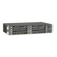
Figure 4: 7705 SAR-8 Front View
44
Csm
45
7705 SAR-8 Overview
45
Figure 5: 7705 SAR-8 Slot Identification
45
Adapter Cards
46
Figure 6: 7705 SAR-8 CSM Features
46
Filler Plates
48
Power System
48
Figure 7: 7705 SAR-8 Adapter Card
48
Figure 8: 7705 SAR-8 Filler Plate
48
Fan Module
49
Distribution Panels and Cables
52
7705 SAR-8 Overview
53
Table 3: Distribution Panel Features
53
Figure 10: BNC Distribution Panel
53
Figure 11: Mini-Coaxial Distribution Panel
54
Figure 12: RJ-45 Distribution Panel
54
Figure 13: 6-Port V.35 Distribution Panel
55
Figure 14: 6-Port V.35 Distribution Panel M34 Pinouts (Female)
55
Figure 15: 6-Port RS-232 Distribution Panel
56
Figure 16: 6-Port RS-232 Distribution Panel DB25 Pinouts (Female)
56
Table 4: T1/E1 Cables
57
Notes on 7705 SAR-8 and 7705 SAR-F
59
Table 5: 7705 SAR-8 and 7705 SAR-F Comparison
59
SAR System Installation Process
61
Site Preparation
63
Warnings and Notes
64
Site Preparation
64
Site Preparation
65
System Specifications
66
Chassis Specifications
66
Environmental Specifications
66
Table 6: 7705 SAR-8 Chassis Specifications
66
Table 7: Environmental Specifications
66
Adapter Card Specifications
68
CSM Specifications
68
Fan Module Specifications
68
Table 8: Adapter Card Specifications
68
Table 9: CSM Specifications
68
Table 10: Fan Module Specifications
68
Component Power Consumption
69
Table 11: Component Power Consumption
69
Component Operating Requirements
70
Table 12: 7705 SAR-8 Hardware Components for DC Operational Requirements
70
Installation Locations
71
Chassis Location Requirements
72
Figure 17: Chassis Clearance Requirements (View from Top)
72
Table 13: Chassis Clearance Specifications
73
Safety Considerations
74
Placement
74
Grounding
74
CBN and IBN Support
75
Cabling
75
Power
76
Fan Module
77
Storage
77
Compliance
77
Table 14: Storage Specifications
77
Installing the Chassis
79
Unpacking the Chassis
80
Unpacking Precautions
80
Table 15: Unpacking the 7705 SAR-8 Chassis
81
Figure 18: Unpacking the 7705 SAR-8 Chassis
81
Installing the Chassis in a Rack
82
Rack-Mounting the Chassis
82
Table 16: Rack-Mounting the 7705 SAR-8 Chassis
83
Figure 19: Installing the 7705 SAR-8 Chassis in a Rack
83
Chassis Ground Wiring
85
Making the Ground Connection
85
Figure 20: Preparing the Ground Wire
85
Table 17: Ground Wire Descriptions
86
Table 18: Chassis Ground Connection
86
Figure 21: Attaching the Chassis Ground Connector
86
DC Power Connections
89
Wiring and Connecting DC Power
90
Warnings and Notes
90
DC Power Connections
90
DC-Input Power Connections
91
Wiring the DC Inputs
91
DC Power Connections
91
Table 19: DC Power Connection Descriptions
92
Figure 22: DC Power Harness
92
Figure 23: Wiring the -48 VDC Power Supplies
92
For -48 VDC Installations
93
Table 20: Wiring the DC Power Supplies Descriptions
93
For +24 VDC Installations
94
Figure 24: Wiring the +24 VDC Power Supplies
94
Installing the Components
95
Installing Components
96
Warnings and Notes
96
Csm
96
Installing the Components
96
Installing the Components
97
Table 21: CSM Installation Features
97
Figure 25: Installing the CSM
97
Compact Flash
98
Fan Module
99
Warnings and Notes
100
Table 22: Fan Module Installation Features
100
Figure 26: Installing the Fan Module
100
Adapter Cards
101
Table 23: Adapter Card Installation Features
102
Figure 27: Installing an Adapter Card
102
Sfps
103
Table 24: SFP Installation Features
104
Figure 28: Installing an SFP
104
Installing a Distribution Panel in a Rack
105
Rack-Mounting a Distribution Panel
105
Figure 29: Installing a Distribution Panel in a Rack
105
Table 25: Rack-Mounting the Distribution Panel
106
Disconnecting a 1.0/2.3 Mini-Coaxial Cable from a Distribution Panel
107
Figure 30: Mini-Coaxial Connector Disconnection Tool
107
Figure 31: Disconnecting a 1.0/2.3 Mini-Coaxial Cable from a Distribution Panel
107
Managing Cable Connections to Adapter Cards
109
Warnings and Notes
109
Ethernet and Copper Cables
110
Figure 32: Managing Cable Connections
110
T3/E3 SFP Connections
111
Fiber Cables
111
Making a Shield Ground Connection
112
Wire Identification by Color
113
Table 26: Quad Identification Wire Color
113
Making External Synchronization Connections
114
Table 27: Redundant External Synchronization Input Features
114
Figure 33: Installing Redundant External Synchronization Inputs
114
Connecting an External Synchronization Input
115
Providing an External Synchronization Output
115
Initializing and Provisioning
117
Powering up the Router
118
Power-Up and Initialization
118
Initializing and Provisioning
118
Troubleshooting Initial Startup
119
Figure 34: Files on the Compact Flash
120
Establishing Router Management Connections
121
Console Connection
121
Table 28: Console Port Default Settings
121
Figure 35: Console Port Connection
121
Telnet Connection
122
Figure 36: Management Port Connection
122
Running Telnet
123
Provisioning CSM and Adapter Card Parameters
124
Card and Card-Type Commands
124
MDA and MDA-Type Commands for Adapter Cards
125
Example
126
Initializing and Provisioning
126
Appendix A: Connectors and Leds
127
CSM Connectors and Leds
128
Appendix A: Connectors and Leds
128
Table 29: 7705 SAR-8 CSM Connector and LED Descriptions
128
Figure 37: CSM Connectors and Leds
128
Fan Module Connectors and Leds
130
Table 30: 7705 SAR-8 Fan Module Connector and LED Descriptions
130
Figure 38: Fan Module Connectors and Leds
130
Adapter Card Connectors and Leds
133
Appendix B: Field-Replaceable Units
135
Warnings and Notes
136
Appendix B: Field-Replaceable Units
136
Replacing a CSM
137
Warnings and Notes
137
Removing a CSM
138
Replacing a CSM
138
Figure 39: Replacing a CSM
138
Replacing Adapter Cards
140
Warnings and Notes
140
Changing the Adapter Card Configuration
141
Removing an Adapter Card
142
Table 31: Adapter Card Installation Features
142
Figure 40: Removing an Adapter Card
142
Replacing an Adapter Card
144
Figure 41: Replacing an Adapter Card
144
Replacing the Fan Module
145
Warnings and Notes
145
Removing the Fan Module
146
Figure 42: Removing the Fan Module
146
Replacing the Fan Module
147
Figure 43: Replacing the Fan Module
147
Installing a Filler Plate
148
Appendix C: Pinout Assignments
149
CSM Ports
150
Management Port
150
Appendix C: Pinout Assignments
150
Figure 44: CSM Ports
150
Figure 45: Management Port Pin Numbers
150
Management Port Pinouts
151
Console Port
151
Table 32: Ethernet Management Port Pinouts-RJ-45 Female
151
Figure 46: Console Port Pin Numbers
151
Console Port Pinouts
152
Table 33: Console Port Pinouts-DB9 Male
152
Fan Module Port
153
External Alarms Port
153
Figure 47: Fan Module Port
153
External Alarms Port Pinouts
154
Table 34: External Alarms Port Pinouts
154
Figure 48: External Alarms Port Pin Numbers
154
Alarm Examples
155
Table 35: Alarm Examples
155
RJ-45 Distribution Panel
156
RJ-45 Distribution Panel Pinouts
156
Table 36: RJ-45 Distribution Panel Pinout Assignments
156
Appendix C: Pinout Assignments
156
Figure 49: RJ-45 Distribution Panel Connector Pin Numbers
156
Adapter Card Ports
157
Standards and Protocol Support
159
Other manuals for Alcatel-Lucent 7705
Installation Guide
176 pages
Configuration Guide
532 pages
Interface Configuration Guide
226 pages
Brochure
2 pages
Service Guide
546 pages
4
Based on 1 rating
Ask a question
Give review
Questions and Answers:
Need help?
Do you have a question about the Alcatel-Lucent 7705 and is the answer not in the manual?
Ask a question
Alcatel-Lucent 7705 Specifications
General
Brand
Alcatel-Lucent
Model
7705
Category
Network Router
Language
English
Related product manuals
Alcatel-Lucent 7705 SAR-A
154 pages
Alcatel-Lucent 7705 SAR-8
304 pages
Alcatel-Lucent 7750
788 pages
Alcatel-Lucent 7750 SR
1948 pages
Alcatel-Lucent 7750 SR OS
1506 pages
Alcatel-Lucent 7750 SR-a4
232 pages
Alcatel-Lucent 7750 SR-a8
232 pages
Alcatel-Lucent 7750 SR OS Basic
484 pages
Alcatel-Lucent 7450
912 pages
Alcatel-Lucent OA5725R
39 pages
Alcatel-Lucent OmniSwitch 6450
136 pages
Alcatel-Lucent OmniSwitch 6860
122 pages