Alesis A4/A8 Amplifiers Service Manual------ 7 03/07/03
2.20 New Case Bracket Insulator(s)
It was found that it was
possible for the insulation on the
wires from the main power
transformer(s) could over time be cut
by the case bracket(s) (one in A4, two
in A8). This could in turn make it
possible for the end-user to be
shocked through the case itself. The
solution was to replace the insulators
with a version that covered those
areas of the metal that could
potentially cut the insulation.
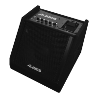
To replace the old insulators,
first remove the rectifier and move the
cables away from the case brackets.
Be sure to examine the wires for any
damage that have already occurred. Then remove the bracket(s) from the chassis. Figure 2
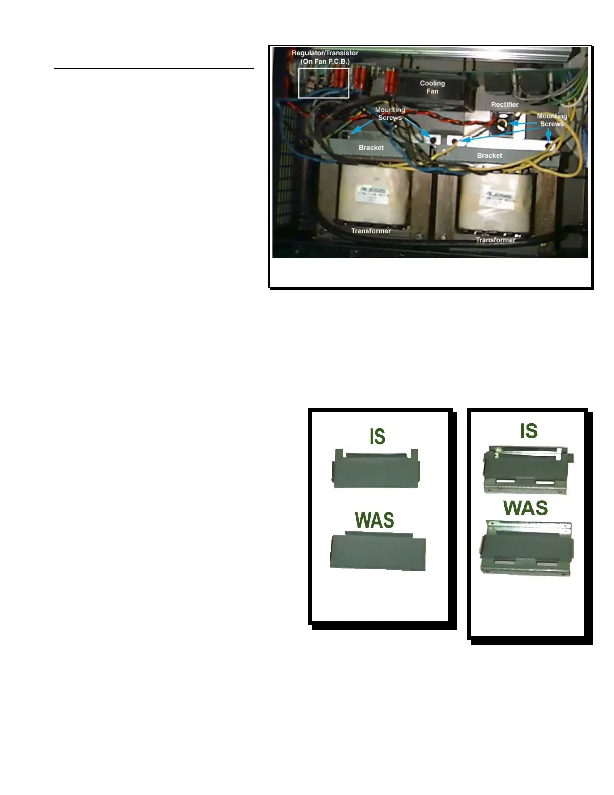
shows the locations of the bracket mounting screws while Figures 3 and 4 show the new and old
styles of insulator (New style Alesis Part # 5-04-1018). Replace the old insulators and
reassemble the brackets and rectifier. Route the wires around the transformer bracket(s) as
shown in Figure 5. In addition, the regulator U5 (A8) U4 (A4) and transistor Q53 (A8) Q39 (A4)
on the Fan PCB (See Figure 2) should be checked to ensure that they do not short to the case.
If necessary, bend these components away from the case bottom and resolder both of them to
ensure a solid connection.
Figure 2 Bracket, Regulator, and Mounting Screw
Locations
Figure 4-New and
Old Inserts On
Brackets
Figure 3-New and Old
Inserts
 Loading...