1
www.observint.com
ALI-CD700_CQ
7/8/14
Power
Connector
Video BNC
Connector
Camera drop cable connectors (all ALI-CD700 series cameras)
What’s in the box
• Camera assembly
• Security L- wrench
• Mounting screws and wall inserts
• This manual
• Drill template
ALI-CD700 (left) and ALI-CD700VF (right) drill templates
Tools you need
To install the camera, you will need:
• 12 Vdc power source. See Specications for voltage and wattage requirements.
• Tools and additional fasteners (may be required) for mounting the camera
• Video and power extension cable
• CCTV video setup monitor (optional)
Installation
Before installation:
• Make sure that the device is in good condition and all the assembly parts are included.
• Check the specication of the products for the installation environment.
• Make sure that the wall or the ceiling is strong enough to withstand 3 times the weight of the camera.
• To avoid re or shock hazard, use only UL listed power supplies. Verify that the power supply will
provide the rated voltage and wattage for the camera. See the Specications section.
During installation:
• Camera Lens: Handle the camera carefully to prevent scratching or soiling the lens. If the lens or IR
array shield becomes soiled, clean it only with approved products. See the
Cleaning section.
• Monitor impedance: Set the monitor impedance switch to 75 .
• Power supply: Camera drop cable: The camera drop cable includes two connectors:
— Video BNC connector: For transmission of the video signal across a coax (75 ) extension
cable.
— Power connector: When applying Vdc power, observe the power polarity. See the picture
above for connector polarity conguration.
1. Using the drill template provided with your camera, mark the location of the screws that anchor the
base plate to the mounting surface. If you are routing the drop cable through base, also mark the
position of the hole for the drop cable.
2. Drill holes for the screws that anchor the base to the ceiling. The mounting hardware provided is
appropriate for most surfaces. However, depending on the surface materials, more appropriate
fasteners may be required.
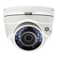
ALI-CD700 Series Infrared Turret
Cameras Quick Installation Guide
ForProducts: ALI-CD700, ALI-CD700G (gray), ALI-CD700VF, ALI-CD700VFG (gray)
The ALIBI ALI-CD700 series turret cameras include a new generation sensor with high sensitivity and
advanced circuit design technology. They feature high resolution, low image distortion and low noise
features which makes them suitable for surveillance and image processing systems.
Features
• High resolution color sensor: 700 TV Lines
• IR LED enables the day/night surveillance
• 2.8 ~ 12 mm Varifocal lens (ALI-CD700VF series only)
• IR cut lter auto switch
• True day/night
• ATW brings high color rendition
• Auto electronic shutter control adapts to dierent surveillance environments
• Auto gain control, adaptive brightness
• High SNR for high-quality image
• 12 Vdc power
• Weather protection: IP66 rated
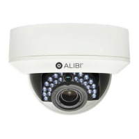
Mounting
plate
IR array
Lens
Camera
module
Enclosure
Clip plate
ALI-CD700 camera assembly
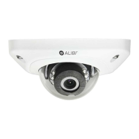
Mounting
plate
Clip plate
Base
assembly
IR array
Lens
Focus
adjust
Zoom
adjust
Camera
module
Enclosure
ALI-CD700VF camera assembly